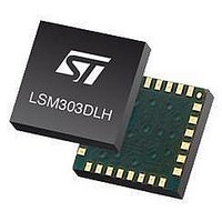
LSM303DLH STMicroelectronics, LSM303DLH Datasheet - Page 18

LSM303DLH
Manufacturer Part Number
LSM303DLH
Description
IC, DIGITAL COMPASS, ±2g ±4g ±8g, LGA-28
Manufacturer
STMicroelectronics
Series
-r
Specifications of LSM303DLH
No. Of Axes
3
Ic Interface Type
I2C, Serial
Sensor Case Style
LGA
No. Of Pins
28
Supply Voltage Range
2.5V To 3.3V
Acceleration Range
± 2g, ± 4g, ± 8g
Sensing Axis
Triple
Acceleration
2 g, 4 g, 8 g
Sensitivity
1 mg/digit, 2 mg/digit, 3.9 mg/digit
Package / Case
LGA-28L
Output Type
Linear
Digital Output - Number Of Bits
16 bit
Supply Voltage (max)
3.3 V
Supply Voltage (min)
2.5 V
Maximum Operating Temperature
+ 85 C
Minimum Operating Temperature
- 30 C
Digital Output - Bus Interface
I2C
Package Type
LGA
Operating Supply Voltage (min)
2.5V
Operating Temperature (max)
85C
Operating Temperature Classification
Commercial
Product Depth (mm)
5mm
Product Height (mm)
1mm
Product Length (mm)
5mm
Mounting
Surface Mount
Pin Count
28
Sensor Type
Accelerometer and Magnetometer
Lead Free Status / Rohs Status
Lead free / RoHS Compliant
For Use With
497-10689 - BOARD ADAPTER LSM303DLH DIL24497-10508 - BOARD EVAL FOR MEMS SENSORS
Available stocks
Company
Part Number
Manufacturer
Quantity
Price
Part Number:
LSM303DLH
Manufacturer:
ST
Quantity:
20 000
Part Number:
LSM303DLHC
Manufacturer:
ST
Quantity:
20 000
Company:
Part Number:
LSM303DLHCTR
Manufacturer:
ST
Quantity:
12 000
Part Number:
LSM303DLHCTR
Manufacturer:
ST
Quantity:
20 000
Company:
Part Number:
LSM303DLHTR
Manufacturer:
ST
Quantity:
8 295
Company:
Part Number:
LSM303DLHTR-SMJ
Manufacturer:
ST
Quantity:
8 305
Functionality
5
5.1
5.2
5.3
18/47
Functionality
The LSM303DLH is a system-in-package featuring a 3D digital linear acceleration and 3D
digital magnetic field detection sensor.
The system includes specific sensing elements and an IC interfaces capable of measuring
both the linear acceleration and magnetic field applied to it, and to provide a signal to the
external world through an I
The sensing system is manufactured using specialized micromachining processes, while
the IC interfaces are realized using a CMOS technology that allows the design of a
dedicated circuit which is trimmed to better match the sensing element characteristics.
The LSM303DLH features two data-ready signals (RDY) which indicate when a new set of
measured acceleration data and magnetic data are available, thus simplifying data
synchronization in the digital system that uses the device.
The LSM303DLH may also be configured to generate an inertial wakeup and free-fall
interrupt signal according to a programmed acceleration event along the enabled axes. Both
free-fall and wakeup can be used simultaneously on two different accelerometer interrupts.
Factory calibration
The IC interface is factory calibrated for linear acceleration sensitivity (LA_So), and linear
acceleration Zero-g level (LA_TyOff).
The trimming values are stored inside the device in non-volatile memory. When the device is
turned on, the trimming parameters are downloaded into the registers to be used during
normal operation. This allows the use of the device without further calibration.
Linear acceleration self-test operation
Self-test allows the checking of sensor functionality without moving it. The self-test function
is off when the self-test bit (ST) of CTRL_REG4_A (control register 4) is programmed to ‘0‘.
When the self-test bit of CTRL_REG4_A is programmed to ‘1‘ an actuation force is applied
to the sensor, simulating a definite input acceleration. In this case the sensor outputs will
exhibit a change in their DC levels which are related to the selected full-scale through the
device sensitivity. When self-test is activated, the device output level is given by the
algebraic sum of the signals produced by the acceleration acting on the sensor and by the
electrostatic test-force. If the output signals change within the amplitude specified in
Table
within the defined specifications.
Magnetic self-test operation
To check the magnetic sensor for proper operation, a self-test feature is incorporated in
which the sensor offset straps are excited to create a nominal field strength (bias field) to be
measured. To implement this self-test, the least significant bits (MS1 and MS0) of
configuration register A are changed from 00 to 01 (0x12 or 0b000xxx01).
3, then the sensor is working properly and the parameters of the interface chip are
2
C serial interface with separated digital ouput.
Doc ID 16941 Rev 1
LSM303DLH


