PCA9555PW NXP Semiconductors, PCA9555PW Datasheet - Page 30
PCA9555PW
Manufacturer Part Number
PCA9555PW
Description
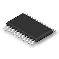
IC, I2C-BUS AND SMBUS I/O PORT, TSSOP24
Manufacturer
NXP Semiconductors
Datasheet
1.PCA9555BS118.pdf
(34 pages)
Specifications of PCA9555PW
Chip Configuration
16 Bit
Bus Frequency
400kHz
Ic Interface Type
I2C
No. Of I/o's
16
Supply Voltage Range
2.3V To 5.5V
Digital Ic Case Style
TSSOP
No. Of Pins
24
Termination Type
SMD
Filter Terminals
SMD
Rohs Compliant
Yes
Lead Free Status / RoHS Status
Lead free / RoHS Compliant
Available stocks
Company
Part Number
Manufacturer
Quantity
Price
Company:

Part Number:
PCA9555PW
Manufacturer:
NXP
Quantity:
3 125
Company:
Part Number:
PCA9555PW
Manufacturer:
NXP Semiconductors
Quantity:
36 610
Part Number:
PCA9555PW
Manufacturer:
PHILIPS
Quantity:
20 000
Company:
Part Number:
PCA9555PW/G
Manufacturer:
MPS
Quantity:
23 062
Part Number:
PCA9555PW/G118
Manufacturer:
PHILIPS/飞利浦
Quantity:
20 000
Part Number:
PCA9555PWR
Manufacturer:
TI/德州仪器
Quantity:
20 000
Part Number:
PCA9555PWRG4
Manufacturer:
TI/德州仪器
Quantity:
20 000


NXP Semiconductors
16. Soldering of through-hole mount packages
PCA9555_8
Product data sheet
16.1 Introduction to soldering through-hole mount packages
16.2 Soldering by dipping or by solder wave
16.3 Manual soldering
For further information on temperature profiles, refer to Application Note AN10365
“Surface mount reflow soldering description” .
This text gives a very brief insight into wave, dip and manual soldering.
Wave soldering is the preferred method for mounting of through-hole mount IC packages
on a printed-circuit board.
Driven by legislation and environmental forces the worldwide use of lead-free solder
pastes is increasing. Typical dwell time of the leads in the wave ranges from
3 seconds to 4 seconds at 250 C or 265 C, depending on solder material applied, SnPb
or Pb-free respectively.
The total contact time of successive solder waves must not exceed 5 seconds.
The device may be mounted up to the seating plane, but the temperature of the plastic
body must not exceed the specified maximum storage temperature (T
printed-circuit board has been pre-heated, forced cooling may be necessary immediately
after soldering to keep the temperature within the permissible limit.
Apply the soldering iron (24 V or less) to the lead(s) of the package, either below the
seating plane or not more than 2 mm above it. If the temperature of the soldering iron bit is
less than 300 C it may remain in contact for up to 10 seconds. If the bit temperature is
between 300 C and 400 C, contact may be up to 5 seconds.
Fig 32. Temperature profiles for large and small components
temperature
MSL: Moisture Sensitivity Level
Rev. 08 — 22 October 2009
= minimum soldering temperature
maximum peak temperature
minimum peak temperature
= MSL limit, damage level
16-bit I
2
C-bus and SMBus I/O port with interrupt
temperature
peak
stg(max)
PCA9555
© NXP B.V. 2009. All rights reserved.
001aac844
). If the
time
30 of 34
Related parts for PCA9555PW
Image
Part Number
Description
Manufacturer
Datasheet
Request
R

Part Number:
Description:
I/O Expanders, Repeaters & Hubs I2C BUS HUB 5-CH
Manufacturer:
NXP Semiconductors
Datasheet:
Part Number:
Description:
I/O Expanders, Repeaters & Hubs I/O EXPANDER W/2K EE
Manufacturer:
NXP Semiconductors
Datasheet:

Part Number:
Description:
NXP Semiconductors designed the LPC2420/2460 microcontroller around a 16-bit/32-bitARM7TDMI-S CPU core with real-time debug interfaces that include both JTAG andembedded trace
Manufacturer:
NXP Semiconductors
Datasheet:

Part Number:
Description:
NXP Semiconductors designed the LPC2458 microcontroller around a 16-bit/32-bitARM7TDMI-S CPU core with real-time debug interfaces that include both JTAG andembedded trace
Manufacturer:
NXP Semiconductors
Datasheet:
Part Number:
Description:
NXP Semiconductors designed the LPC2468 microcontroller around a 16-bit/32-bitARM7TDMI-S CPU core with real-time debug interfaces that include both JTAG andembedded trace
Manufacturer:
NXP Semiconductors
Datasheet:
Part Number:
Description:
NXP Semiconductors designed the LPC2470 microcontroller, powered by theARM7TDMI-S core, to be a highly integrated microcontroller for a wide range ofapplications that require advanced communications and high quality graphic displays
Manufacturer:
NXP Semiconductors
Datasheet:
Part Number:
Description:
NXP Semiconductors designed the LPC2478 microcontroller, powered by theARM7TDMI-S core, to be a highly integrated microcontroller for a wide range ofapplications that require advanced communications and high quality graphic displays
Manufacturer:
NXP Semiconductors
Datasheet:
Part Number:
Description:
The Philips Semiconductors XA (eXtended Architecture) family of 16-bit single-chip microcontrollers is powerful enough to easily handle the requirements of high performance embedded applications, yet inexpensive enough to compete in the market for hi
Manufacturer:
NXP Semiconductors
Datasheet:
Part Number:
Description:
The XA-S3 device is a member of Philips Semiconductors? XA(eXtended Architecture) family of high performance 16-bitsingle-chip microcontrollers
Manufacturer:
NXP Semiconductors
Datasheet:

Part Number:
Description:
The NXP BlueStreak LH75401/LH75411 family consists of two low-cost 16/32-bit System-on-Chip (SoC) devices
Manufacturer:
NXP Semiconductors
Datasheet:
Part Number:
Description:
The NXP LPC3130/3131 combine an 180 MHz ARM926EJ-S CPU core, high-speed USB2
Manufacturer:
NXP Semiconductors
Datasheet:
Part Number:
Description:
The NXP LPC3141 combine a 270 MHz ARM926EJ-S CPU core, High-speed USB 2
Manufacturer:
NXP Semiconductors
Part Number:
Description:
The NXP LPC3143 combine a 270 MHz ARM926EJ-S CPU core, High-speed USB 2
Manufacturer:
NXP Semiconductors

Part Number:
Description:
The NXP LPC3152 combines an 180 MHz ARM926EJ-S CPU core, High-speed USB 2
Manufacturer:
NXP Semiconductors