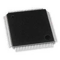
LAN9215-MT SMSC, LAN9215-MT Datasheet - Page 41

LAN9215-MT
Manufacturer Part Number
LAN9215-MT
Description
CONTROLLER, ENET, NON-PCI, 100TQFP
Manufacturer
SMSC
Specifications of LAN9215-MT
Data Rate
100Mbps
No. Of Ports
2
Ethernet Type
IEEE 802.3 / 802.3u
Supply Current
40mA
Supply Voltage Range
2.97V To 3.63V
Operating Temperature Range
0°C To +70°C
Digital Ic Case Style
TQFP
Interface Type
HBI
Rohs Compliant
Yes
Lead Free Status / RoHS Status
Lead free / RoHS Compliant
Available stocks
Company
Part Number
Manufacturer
Quantity
Price
Company:
Part Number:
LAN9215-MT
Manufacturer:
BROADCOM
Quantity:
450
Company:
Part Number:
LAN9215-MT
Manufacturer:
Standard
Quantity:
1 643
Company:
Part Number:
LAN9215-MT
Manufacturer:
SMSC
Quantity:
9
Part Number:
LAN9215-MT
Manufacturer:
SMSC
Quantity:
20 000
Highly Efficient Single-Chip 10/100 Ethernet Controller with HP Auto-MDIX and Industrial Temperature Support
Datasheet
SMSC
3.9.3.2
3.10
PHY REG 0.15
SOURCE
RESET
LAN9215i
PHY_RST
nRESET
SRST
POR
Energy Detect Power-Down
This power-down mode is activated by setting the Phy register bit 17.13 to 1. Please refer to
5.5.8, "Mode Control/Status," on page 115
no energy is present on the line, the PHY is powered down, with the exception of the management
interface, the SQUELCH circuit and the ENERGYON logic. The ENERGYON logic is used to detect
the presence of valid energy from 100Base-TX, 10Base-T, or Auto-negotiation signals
In this mode, when the ENERGYON signal is low, the PHY is powered-down, and nothing is
transmitted. When energy is received - link pulses or packets - the ENERGYON signal goes high, and
the PHY powers-up. It automatically resets itself into the state it had prior to power-down, and asserts
the INT7.1 bit of the register defined in
ENERGYON interrupt is enabled, this event will cause an interrupt to the host. The first and possibly
the second packet to activate ENERGYON may be lost. When 17.13 is low, energy detect power-down
is disabled.
The LAN9215i has five reset sources:
Table 3.10
Note 3.10 After any PHY reset, the application must wait until the “Link Status” bit in the PHY’s “Basic
Note 3.11 After a POR, nRESET or SRST, the LAN9215i will automatically check for the presence
Note 3.12 HBI - “Host Bus Interface”, NASR - Not affected by software reset.
Detailed Reset Description
Power-On Reset (POR)
Hardware Reset Input Pin (nRESET)
Soft Reset (SRST)
PHY Soft Reset via PMT_CTRL bit 10 (PHY_RST)
PHY Soft Reset via PHY Basic Control Register (PHY REG 0.15)
PLL
X
X
shows the effect of the various reset sources on the LAN9215i's circuitry.
Status Register” (PHY Reg. 1.2) is set before attempting to transmit or receive data.
of an external EEPROM. After any of these resets the application must verify that the EPC
Busy Bit (E2P_CMD, bit 31) is cleared before attempting to access the EEPROM, or
change the function of the GPO/GPIO signals, or before modifying the ADDRH or ADDRL
registers in the MAC.
Note
HBI
3.12
X
X
X
Table 3.10 Reset Sources and Affected Circuitry
REGISTERS
Note 3.12
NASR
X
X
DATASHEET
MIL
X
X
X
Section 5.5.11, "Interrupt Source Flag," on page
for additional information on this register. In this mode when
41
MAC
X
X
X
Note 3.10
PHY
X
X
X
X
EEPROM MAC
RELOAD
Note 3.11
ADDR.
X
X
X
Revision 1.93 (12-12-07)
LATCHED
CONFIG.
STRAPS
118. If the
X
X
Section


