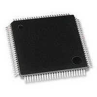
LAN9215-MT SMSC, LAN9215-MT Datasheet - Page 29

LAN9215-MT
Manufacturer Part Number
LAN9215-MT
Description
CONTROLLER, ENET, NON-PCI, 100TQFP
Manufacturer
SMSC
Specifications of LAN9215-MT
Data Rate
100Mbps
No. Of Ports
2
Ethernet Type
IEEE 802.3 / 802.3u
Supply Current
40mA
Supply Voltage Range
2.97V To 3.63V
Operating Temperature Range
0°C To +70°C
Digital Ic Case Style
TQFP
Interface Type
HBI
Rohs Compliant
Yes
Lead Free Status / RoHS Status
Lead free / RoHS Compliant
Available stocks
Company
Part Number
Manufacturer
Quantity
Price
Company:
Part Number:
LAN9215-MT
Manufacturer:
BROADCOM
Quantity:
450
Company:
Part Number:
LAN9215-MT
Manufacturer:
Standard
Quantity:
1 643
Company:
Part Number:
LAN9215-MT
Manufacturer:
SMSC
Quantity:
9
Part Number:
LAN9215-MT
Manufacturer:
SMSC
Quantity:
20 000
Highly Efficient Single-Chip 10/100 Ethernet Controller with HP Auto-MDIX and Industrial Temperature Support
Datasheet
SMSC
FIELD
FIELD
FIELD
FIELD
30:0
15:0
2:1
7:0
31
LAN9215i
3
0
The Filter i command register controls Filter i operation.
The Filter i Offset register defines the offset in the frame’s destination address field from which the
frames are examined by Filter i.
The Filter i CRC-16 register contains the CRC-16 result of the frame that should pass Filter i.
Table 3.6
DESCRIPTION
Must be zero (0)
Byte Mask: If bit j of the byte mask is set, the CRC machine processes byte number pattern - (offset
+ j) of the incoming frame. Otherwise, byte pattern - (offset + j) is ignored.
DESCRIPTION
Address Type: Defines the destination address type of the pattern. When bit is set, the pattern
applies
only to multicast frames. When bit is cleared, the pattern applies only to unicast frames.
RESERVED
Enable Filter: When bit is set, Filter i is enabled, otherwise, Filter i is disabled.
DESCRIPTION
Pattern Offset: The offset of the first byte in the frame on which CRC is checked for wake-up frame
recognition. The minimum value of this field must be 12 since there should be no CRC check for
the destination address and the source address fields. The MAC checks the first offset byte of the
frame for CRC and checks to determine whether the frame is a wake-up frame. Offset 0 is the first
byte of the incoming frame's destination address.
DESCRIPTION
Pattern CRC-16: This field contains the 16-bit CRC value from the pattern and the byte mask
programmed to the wake-up filter register Function. This value is compared against the CRC
calculated on the incoming frame, and a match indicates the reception of a wakeup frame.
describes the Filter i CRC-16 bit fields.
Table 3.3 Filter i Byte Mask Bit Definitions
Table 3.4 Filter i Command Bit Definitions
Table 3.6 Filter i CRC-16 Bit Definitions
Table 3.5 Filter i Offset Bit Definitions
FILTER I BYTE MASK DESCRIPTION
FILTER I OFFSET DESCRIPTION
FILTER I CRC-16 DESCRIPTION
FILTER i COMMANDS
Table 3.5
DATASHEET
29
describes the Filter i Offset bit fields.
Table 3.4
shows the Filter I command register.
Revision 1.93 (12-12-07)


