LIS302DLH STMicroelectronics, LIS302DLH Datasheet - Page 26
LIS302DLH
Manufacturer Part Number
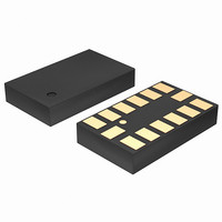
LIS302DLH
Description
SENSOR ACCELEROMETER 3AXIS 14LGA
Manufacturer
STMicroelectronics
Datasheet
1.LIS302DLH.pdf
(37 pages)
Specifications of LIS302DLH
Featured Product
STM32 Cortex-M3 Companion Products
Axis
X, Y, Z
Acceleration Range
±2.3g, 9.2g
Sensitivity
18mg/digit, 72mg/digit
Voltage - Supply
2.16 V ~ 3.6 V
Output Type
Digital
Bandwidth
100Hz ~ 400Hz Selectable
Interface
I²C, SPI
Mounting Type
Surface Mount
Package / Case
14-LGA
Package Type
LGA
Operating Supply Voltage (min)
2.16V
Operating Supply Voltage (typ)
2.5V
Operating Supply Voltage (max)
3.6V
Operating Temperature (min)
-40C
Operating Temperature (max)
85C
Operating Temperature Classification
Industrial
Product Depth (mm)
3mm
Product Height (mm)
0.92mm
Product Length (mm)
5mm
Mounting
Surface Mount
Pin Count
14
Sensing Axis
Triple
Acceleration
2 g, 4 g, 8 g
Digital Output - Number Of Bits
16 bit
Supply Voltage (max)
3.6 V
Supply Voltage (min)
2.16 V
Maximum Operating Temperature
+ 85 C
Minimum Operating Temperature
- 40 C
Digital Output - Bus Interface
I2C, SPI
Lead Free Status / RoHS Status
Lead free / RoHS Compliant
Other names
497-10052
Available stocks
Company
Part Number
Manufacturer
Quantity
Price
Company:

Part Number:
LIS302DLHS0.5
Manufacturer:
INNOLUX
Quantity:
1 000
Company:
Part Number:
LIS302DLHTR
Manufacturer:
SANYO
Quantity:
11


Register description
26/37
Table 22.
BOOT bit is used to refresh the content of internal registers stored in the flash memory
block. At the device power up the content of the flash memory block is transferred to the
internal registers related to trimming functions to permit a good behavior of the device itself.
If for any reason the content of trimming registers was changed it is sufficient to use this bit
to restore correct values. When BOOT bit is set to ‘1’ the content of internal flash is copied
inside corresponding internal registers and it is used to calibrate the device. These values
are factory trimmed and they are different for every accelerometer. They permit a good
behavior of the device and normally they have not to be changed. At the end of the boot
process the BOOT bit is set again to ‘0’.
Table 23.
HPCF[1:0]. These bits are used to configure high-pass filter cut-off frequency f
given by:
The equation can be simplified to the following approximated equation:
Table 24.
HPen2
HPen1
HPCF1,
HPCF0
HPcoeff2,1
00
01
10
11
HPM1
0
0
1
CTRL_REG2 description (continued)
High-pass filter mode configuration
High-pass filter cut-off frequency configuration
Data rate = 50 Hz
High pass filter enabled for interrupt 2 source. Default value: 0
(0: filter bypassed; 1: filter enabled)
High pass filter enabled for interrupt 1 source. Default value: 0
(0: filter bypassed; 1: filter enabled)
High pass filter cut-off frequency configuration. Default value: 00
(00: HPc=8; 01: HPc=16; 10: HPc=32; 11: HPc=64)
f
0.125
t
0.25
0.5
[Hz]
1
HPM0
0
1
0
Doc ID 15797 Rev 1
Data rate = 100 Hz
f
t
Normal mode (reset reading HP_RESET_FILTER)
Reference signal for filtering
Normal mode (reset reading HP_RESET_FILTER)
=
f
f
t
0.25
ln
t
0.5
[Hz]
2
1
⎛
⎝
=
1
--------------------- -
6
–
⋅
----------- -
HPc
f
1
HPc
s
⎞
⎠
⋅
Data rate = 400 Hz
High-pass filter mode
------
2π
f
s
f
t
[Hz]
8
4
2
1
Data rate = 1000 Hz
t
f
t
LIS302DLH
which is
2.5
[Hz]
20
10
5
Related parts for LIS302DLH
Image
Part Number
Description
Manufacturer
Datasheet
Request
R

Part Number:
Description:
STMicroelectronics [RIPPLE-CARRY BINARY COUNTER/DIVIDERS]
Manufacturer:
STMicroelectronics
Datasheet:
Part Number:
Description:
STMicroelectronics [LIQUID-CRYSTAL DISPLAY DRIVERS]
Manufacturer:
STMicroelectronics
Datasheet:

Part Number:
Description:
BOARD EVAL FOR MEMS SENSORS
Manufacturer:
STMicroelectronics
Datasheet:
Part Number:
Description:
NPN TRANSISTOR POWER MODULE
Manufacturer:
STMicroelectronics
Datasheet:
Part Number:
Description:
TURBOSWITCH ULTRA-FAST HIGH VOLTAGE DIODE
Manufacturer:
STMicroelectronics
Datasheet:
Part Number:
Description:
Manufacturer:
STMicroelectronics
Datasheet:
Part Number:
Description:
DIODE / SCR MODULE
Manufacturer:
STMicroelectronics
Datasheet:
Part Number:
Description:
DIODE / SCR MODULE
Manufacturer:
STMicroelectronics
Datasheet:
Part Number:
Description:
Search -----> STE16N100
Manufacturer:
STMicroelectronics
Datasheet:
Part Number:
Description:
Search ---> STE53NA50
Manufacturer:
STMicroelectronics
Datasheet:
Part Number:
Description:
NPN Transistor Power Module
Manufacturer:
STMicroelectronics
Datasheet:
Part Number:
Description:
DIODE / SCR MODULE
Manufacturer:
STMicroelectronics
Datasheet: