LIS35DETR STMicroelectronics, LIS35DETR Datasheet - Page 14
LIS35DETR
Manufacturer Part Number
LIS35DETR
Description
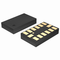
IC ACCELEROMETER 3AXIS 14LGA
Manufacturer
STMicroelectronics
Datasheet
1.LIS35DETR.pdf
(39 pages)
Specifications of LIS35DETR
Axis
X, Y, Z
Acceleration Range
±2.3g, 9.2g
Sensitivity
18mg/digit, 72mg/digit
Voltage - Supply
2.16 V ~ 3.6 V
Output Type
Digital
Bandwidth
100Hz ~ 400Hz Selectable
Interface
I²C, SPI
Mounting Type
Surface Mount
Package / Case
14-LGA
Sensing Axis
X, Y, Z
Acceleration
2 g, 8 g
Digital Output - Number Of Bits
8 bit
Supply Voltage (max)
3.6 V
Supply Voltage (min)
2.16 V
Supply Current
0.3 mA
Maximum Operating Temperature
+ 85 C
Minimum Operating Temperature
- 40 C
Digital Output - Bus Interface
I2C, SPI
Mounting Style
SMD/SMT
Shutdown
Yes
Lead Free Status / RoHS Status
Lead free / RoHS Compliant
Available stocks
Company
Part Number
Manufacturer
Quantity
Price

Part Number:
LIS35DETR
Manufacturer:
ST
Quantity:
20 000


Mechanical and electrical specifications
2.5
2.5.1
2.5.2
2.5.3
14/39
Terminology
Sensitivity
Sensitivity describes the gain of the sensor and can be determined e.g. by applying 1g
acceleration to it. As the sensor can measure DC accelerations this can be done easily by
pointing the axis of interest towards the center of the Earth, noting the output value, rotating
the sensor by 180 degrees (point to the sky) and noting the output value again. By doing so,
±1g acceleration is applied to the sensor. Subtracting the larger output value from the
smaller one and dividing the result by 2 leads to the actual sensitivity of the sensor. This
value changes very little over temperature and also very little over time. The Sensitivity
Tolerance describes the range of Sensitivities of a large population of sensor.
Zero-g level
Zero-g level Offset (Off) describes the deviation of an actual output signal from the ideal
output signal if there is no acceleration present. A sensor in a steady state on a horizontal
surface will measure 0g in X axis and 0g in Y axis whereas the Z axis will measure 1g. The
output is ideally in the middle of the dynamic range of the sensor (content of OUT registers
00h, data expressed as 2’s complement number). A deviation from ideal value in this case is
called Zero-g offset. Offset is to some extent a result of stress to a precise MEMS sensor
and therefore the offset can slightly change after mounting the sensor onto a printed circuit
board or exposing it to extensive mechanical stress. Offset changes little over temperature,
see “Zero-g level change vs. temperature”. The Zero-g level of an individual sensor is stable
over lifetime. The Zero-g level tolerance describes the range of Zero-g levels of a population
of sensors.
Click and double click recognition
The click and double click recognition functions help to create man-machine interface with
little software overload. The device can be configured to output an interrupt signal on
dedicated pin when tapped in any direction.
If the sensor is exposed to a single input stimulus it generates an interrupt request on inertial
interrupt pin (INT1 and/or INT2). A more advanced feature allows to generate and interrupt
request when a “double click” with programmable time between the two events enabling a
“mouse button like” use.
This function can be fully programmed by the user in terms of expected amplitude and
timing of the stimuli.
Doc ID 15594 Rev 1
LIS35DE
Related parts for LIS35DETR
Image
Part Number
Description
Manufacturer
Datasheet
Request
R

Part Number:
Description:
STMicroelectronics [RIPPLE-CARRY BINARY COUNTER/DIVIDERS]
Manufacturer:
STMicroelectronics
Datasheet:
Part Number:
Description:
STMicroelectronics [LIQUID-CRYSTAL DISPLAY DRIVERS]
Manufacturer:
STMicroelectronics
Datasheet:

Part Number:
Description:
BOARD EVAL FOR MEMS SENSORS
Manufacturer:
STMicroelectronics
Datasheet:
Part Number:
Description:
NPN TRANSISTOR POWER MODULE
Manufacturer:
STMicroelectronics
Datasheet:
Part Number:
Description:
TURBOSWITCH ULTRA-FAST HIGH VOLTAGE DIODE
Manufacturer:
STMicroelectronics
Datasheet:
Part Number:
Description:
Manufacturer:
STMicroelectronics
Datasheet:
Part Number:
Description:
DIODE / SCR MODULE
Manufacturer:
STMicroelectronics
Datasheet:
Part Number:
Description:
DIODE / SCR MODULE
Manufacturer:
STMicroelectronics
Datasheet:
Part Number:
Description:
Search -----> STE16N100
Manufacturer:
STMicroelectronics
Datasheet:
Part Number:
Description:
Search ---> STE53NA50
Manufacturer:
STMicroelectronics
Datasheet:
Part Number:
Description:
NPN Transistor Power Module
Manufacturer:
STMicroelectronics
Datasheet:
Part Number:
Description:
DIODE / SCR MODULE
Manufacturer:
STMicroelectronics
Datasheet: