ADIS16204BCCZ Analog Devices Inc, ADIS16204BCCZ Datasheet - Page 15
ADIS16204BCCZ
Manufacturer Part Number
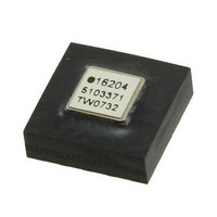
ADIS16204BCCZ
Description
IC ACCEL DIGITAL HI-G 16-LGA
Manufacturer
Analog Devices Inc
Datasheet
1.ADIS16204PCBZ.pdf
(24 pages)
Specifications of ADIS16204BCCZ
Acceleration Range
±37g, 70g
Axis
X, Y
Sensitivity
17.125 LSB/mg, 8.407 LSB/mg
Voltage - Supply
3 V ~ 3.6 V
Output Type
Digital
Bandwidth
400Hz
Interface
SPI
Mounting Type
Surface Mount
Package / Case
16-LGA
No. Of Axes
2
Sensor Case Style
LGA
No. Of Pins
16
Supply Voltage Range
3V To 3.6V
Operating Temperature Range
-40°C To +105°C
Svhc
No SVHC (18-Jun-2010)
Family Name
ADIS16204
Package Type
LGA
Operating Supply Voltage (min)
3V
Operating Supply Voltage (typ)
3.3V
Operating Supply Voltage (max)
3.6V
Operating Temperature (min)
-40C
Operating Temperature (max)
105C
Operating Temperature Classification
Industrial
Product Depth (mm)
8mm
Product Height (mm)
5.2mm
Product Length (mm)
8mm
Mounting
Surface Mount
Pin Count
16
Interface Type
SPI
Sensitivity Per Axis
17.125mg / LSB
Rohs Compliant
Yes
Lead Free Status / RoHS Status
Lead free / RoHS Compliant
For Use With
ADIS16204/PCBZ - BOARD EVAL FOR ADIS16204/PCB
Lead Free Status / Rohs Status
Compliant
Available stocks
Company
Part Number
Manufacturer
Quantity
Price
Company:

Part Number:
ADIS16204BCCZ
Manufacturer:
ST
Quantity:
390


GLOBAL COMMANDS
The ADIS16204 provides global commands, which simplify
many common operations. The COMMAND register provides
command bits for each function. Writing a 1 to the assigned
command bit exercises its function. The flash update copies the
contents of all nonvolatile registers into their assigned, nonvolatile,
flash memory locations. This process takes approximately 50 ms
and requires a power supply that is within the specified operating
range. After waiting the appropriate time for the flash update to
complete, verify successful completion by reading the STATUS
register (flash update error = zero, if successful). If the flash
update was not successful, reading this error bit accomplishes
two things: (1) alert system processor to try again, and (2) clear
the error flag, which is required for flash memory access.
The software reset command restarts the internal processor,
which loads all registers with the contents in their flash memory
locations. The DAC data latch command loads the contents of
AUX_DAC into the DAC latches. Because the AUX_DAC
contents must be updated one byte at a time, this command
ensures a stable DAC output voltage during updates.
Calibration Commands
The autonull command provides a simple method for removing
offset from the sensor outputs. This command takes separate
64-sample measurements for each axis (X, Y), then loads the
opposite value into each axis’ offset null register. The accuracy
of this operation depends on zero force or motion during the
64-sample timeframe. The factory calibration restore sets the
scale and offset null registers (XACCL_NULL, for example)
back to their default values. For more information on
ADIS16204 calibration, see the Calibration section.
Event Capture Commands
The COMMAND register provides four different functions that
simplify the process of using the event capture function. The
reset-capture pointer function sets the contents of the capture
pointer to its initial value of 0x0001. The clear capture flash,
clear capture buffer, and capture flash copy commands are self-
descriptive. The capture flash copy takes approximately 120 ms
to complete and serves the purpose of copying the capture buffer
into nonvolatile flash memory. See the Alarm Detection and
Event Capture section for more information.
Table 8. COMMAND Register Definition
Address
0x3F, 0x3E
Default
N/A
Format
N/A
Access
W only
Rev. B | Page 15 of 24
Table 9. COMMAND Bit Descriptions
Bit
15:11
10
9
8
7
6
5
4
3
2
1
0
CALIBRATION
In addition to the factory calibration, the ADIS16204 provides
a user configurable calibration for systems that require accuracy
improvements. For example, a vehicle system may require better
resolution to separate a minor bump from a hard brake event.
In cases like this, the ADIS16204 provides configuration registers
that adjust both offset and sensitivity (gain) on both X- and
Y-axes. The following relationship describes the calibration
function:
where:
y is the calibrated output data.
m is the scale factor multiplier [XACCL_SCALE/YACCL_SCALE].
x is the precalibration data.
b is the offset adder [XACCL_NULL/YACCL_NULL].
Assuming zero offset and nominal scale factor (sensitivity),
the offset adjustment range for the X-axis is ±35.054 g and
±17.527 g for the Y-axis. Assuming zero offset, the scale factor
adjustment range is 0 to 2.
Table 10. XACCL_NULL Register Definition
Address
0x11, 0x10
1
Table 11. YACCL_NULL Register Definition
Address
0x13, 0x12
1
Table 12. XACCL_SCALE Register Definition
Address
0x15, 0x14
1
2
Scale is the weight of each LSB.
Scale is the weight of each LSB.
Scale is the weight of each LSB.
Equates to a scale factor of one.
y = mx + b
Description
Not used
Reset-capture pointer (set CAPT_PNTR to 0x0001)
Clear capture flash (nonvolatile back-up)
Clear capture buffer (SRAM)
Software reset
Copy capture buffer to nonvolatile flash
Clear peak output registers, (reset them to 0x0000)
Clear status register (reset all bits to 0)
Flash update—saves nonvolatile register settings
DAC data latch
Factory calibration restore
Autonull
Scale
8.407 mg
Scale
Scale
0.0488%
17.125 mg
1
1
1
Default
0x0000
Default
0x0000
Default
0x0800
2
Format
Twos
complement
Format
Twos
complement
Binary
Format
ADIS16204
Access
R/W
Access
R/W
Access
R/W
Related parts for ADIS16204BCCZ
Image
Part Number
Description
Manufacturer
Datasheet
Request
R

Part Number:
Description:
±1.7g Dual-Axis IMEMS Accelerometer Evaluation Board
Manufacturer:
Analog Devices Inc
Datasheet:

Part Number:
Description:
Inertial Sensor Evaluation System
Manufacturer:
Analog Devices Inc
Datasheet:
Part Number:
Description:
Manufacturer:
Analog Devices Inc
Datasheet:
Part Number:
Description:
Manufacturer:
Analog Devices Inc
Datasheet:
Part Number:
Description:
Manufacturer:
Analog Devices Inc
Datasheet:
Part Number:
Description:
Manufacturer:
Analog Devices Inc
Datasheet:
Part Number:
Description:
Manufacturer:
Analog Devices Inc
Datasheet:
Part Number:
Description:
Manufacturer:
Analog Devices Inc
Datasheet:
Part Number:
Description:
Manufacturer:
Analog Devices Inc
Datasheet:
Part Number:
Description:
Manufacturer:
Analog Devices Inc
Datasheet:
Part Number:
Description:
Manufacturer:
Analog Devices Inc
Datasheet:
Part Number:
Description:
Manufacturer:
Analog Devices Inc
Datasheet:
Part Number:
Description:
Manufacturer:
Analog Devices Inc
Datasheet: