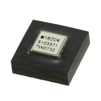
ADIS16204BCCZ Analog Devices Inc, ADIS16204BCCZ Datasheet - Page 14

ADIS16204BCCZ
Manufacturer Part Number
ADIS16204BCCZ
Description
IC ACCEL DIGITAL HI-G 16-LGA
Manufacturer
Analog Devices Inc
Datasheet
1.ADIS16204PCBZ.pdf
(24 pages)
Specifications of ADIS16204BCCZ
Acceleration Range
±37g, 70g
Axis
X, Y
Sensitivity
17.125 LSB/mg, 8.407 LSB/mg
Voltage - Supply
3 V ~ 3.6 V
Output Type
Digital
Bandwidth
400Hz
Interface
SPI
Mounting Type
Surface Mount
Package / Case
16-LGA
No. Of Axes
2
Sensor Case Style
LGA
No. Of Pins
16
Supply Voltage Range
3V To 3.6V
Operating Temperature Range
-40°C To +105°C
Svhc
No SVHC (18-Jun-2010)
Family Name
ADIS16204
Package Type
LGA
Operating Supply Voltage (min)
3V
Operating Supply Voltage (typ)
3.3V
Operating Supply Voltage (max)
3.6V
Operating Temperature (min)
-40C
Operating Temperature (max)
105C
Operating Temperature Classification
Industrial
Product Depth (mm)
8mm
Product Height (mm)
5.2mm
Product Length (mm)
8mm
Mounting
Surface Mount
Pin Count
16
Interface Type
SPI
Sensitivity Per Axis
17.125mg / LSB
Rohs Compliant
Yes
Lead Free Status / RoHS Status
Lead free / RoHS Compliant
For Use With
ADIS16204/PCBZ - BOARD EVAL FOR ADIS16204/PCB
Lead Free Status / Rohs Status
Compliant
Available stocks
Company
Part Number
Manufacturer
Quantity
Price
Company:
Part Number:
ADIS16204BCCZ
Manufacturer:
ST
Quantity:
390
ADIS16204
PROGRAMMING AND CONTROL
CONTROL REGISTER OVERVIEW
The ADIS16204 offers many programmable features controlled
by writing commands to the appropriate control registers. The
following features are available for configuration:
Table 7. Control Register Mapping
Name
ENDURANCE
XACCL_NULL
YACCL_NULL
XACCL_SCALE
YACCL_SCALE
CAP_BUF_1
CAP_BUF_2
ALM_MAG1
ALM_MAG2
ALM_CTRL
CAPT_PNTR
AUX_DAC
GPIO_CTRL
MSC_CTRL
SMPL_PRD
CAPT_CFG
SLP_CNT
STATUS
COMMAND
1
2
In order to establish nonvolatile status, the flash memory must be updated after updating the control registers.
Bit 8 clears after the internal self-test sequence completes, effectively making this bit volatile.
Global commands
Calibration
Operational control
Operational status and diagnostics
Event capture
Sample rate
Power management
DAC output
Digital I/O
Self-test
Status conditions
Alarms
R
R/W
R/W
R/W
R/W
R
R
R/W
R/W
R/W
R/W
R/W
R/W
R/W
R/W
R/W
W
R
W
Type
Volatility
Nonvolatile
Nonvolatile
Nonvolatile
Nonvolatile
Nonvolatile
Volatile
Volatile
Nonvolatile
Nonvolatile
Nonvolatile
Volatile
Volatile
Volatile
Nonvolatile
Nonvolatile
Nonvolatile
Volatile
Volatile
N/A
1
2
Address
0x01, 0x00
0x02 to 0x0F
0x11, 0x10
0x13, 0x12
0x15, 0x14
0x17, 0x16
0x18 to to 0x1B
0x1D, 0x1C
0x1F, 0x1E
0x21, 0x20
0x23, 0x22
0x24 to 0x27
0x29, 0x28
0x2B, 0x2A
0x2A to 0x2F
0x31, 0x30
0x33, 0x32
0x35, 0x34
0x37, 0x36
0x39, 0x38
0x3B, 0x3A
0x3D, 0x3C
0x3F, 0x3E
Bytes
2
14
2
2
2
2
4
2
2
2
2
2
2
2
6
2
2
2
2
2
2
2
2
Rev. B | Page 14 of 24
Function
Flash memory write counter
Output data registers
X-axis offset null calibration register
Y-axis offset null calibration register
X-axis scale factor calibration register
Y-axis scale factor calibration register
Output data registers
Capture buffer output register 1
Capture buffer output register 2
Alarm 1 amplitude threshold
Alarm 2 amplitude threshold
Reserved
Alarm source control register
Capture register address pointer
Reserved
Auxiliary DAC data
Auxiliary digital I/O control register
Miscellaneous control register
ADC sample period control register
Capture configuration register
Counter used to determine length of
power-down mode
System status register
System command register
CONTROL REGISTER STRUCTURE
The ADIS16204 uses a temporary, SRAM-based memory struc-
ture to facilitate the control registers displayed in Table 7. The
start-up configuration is stored in a flash memory structure that
automatically loads into the control registers during the start-up
sequence. Each nonvolatile register has a corresponding flash
memory location for storing the latest configuration contents.
Because flash memory has endurance limitations, the contents
of each nonvolatile register must be stored to flash manually.
Note that the contents of the control register are only nonvola-
tile when they are stored to flash. The flash update command,
made available in the COMMAND register, provides this function.
The ENDURANCE register provides a counter, which allows
for memory reliability management against the flash memory’s
write cycle specification.
Reference Table
Table 26
Table 6
Table 10
Table 11
Table 12
Table 13
Table 6
Table 37, Table 38
Table 37, Table 38
Table 32, Table 34
Table 33, Table 34
Table 30, Table 31
Table 39, Table 40
Table 19, Table 20
Table 21, Table 22
Table 24, Table 25
Table 15, Table 16
Table 35, Table 36
Table 17, Table 18
Table 27, Table 28
Table 8, Table 9


