EVB-USB2412 SMSC, EVB-USB2412 Datasheet - Page 21
EVB-USB2412
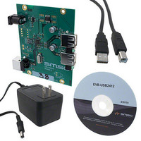
Manufacturer Part Number
EVB-USB2412
Description
EVALUATION BOARD FOR USB2412
Manufacturer
SMSC
Specifications of EVB-USB2412
Design Resources
EVB-USB2412 Schematic EVB-USB2412 BOM
Main Purpose
Interface, USB 2.0 Hub
Embedded
No
Utilized Ic / Part
USB2421
Primary Attributes
Dual Port Hub, High Speed (480Mbps)
Secondary Attributes
Single 5V Supply
Lead Free Status / RoHS Status
Lead free / RoHS Compliant
Other names
638-1106


2-Port USB 2.0 Hi-Speed Hub Controller
Datasheet
Chapter 6 AC Specifications
SMSC USB2412
6.1
C
C
C
C
C
C
C
SYMBOL
0
L
B
S
XTAL
1
2
C
C
Parallel Resonant, Fundamental Mode, 24 MHz ±350 ppm.
Note 6.1
Note 6.2
Oscillator/Crystal
2
1
Crystal shunt capacitance
Crystal load capacitance
Total board or trace
capacitance
Stray capacitance
XTAL pin input capacitance
Load capacitors installed on
OEM board
C
0
C
and should be set to ‘0’ for use in the calculation of the capacitance formulas in
"Formula to Find the Value of C1 and
parasitic capacitance between XTALIN and XTALOUT. For an accurate calculation of C
and C
Each of these capacitance values is typically approximately 18 pF.
0
DESCRIPTION
is usually included (subtracted by the crystal manufacturer) in the specification for C
Figure 6.2 Formula to Find the Value of C
2,
Crystal
take the parasitic capacitance between traces XTALIN and XTALOUT into account.
Figure 6.1 Typical Crystal Circuit
Table 6.1 Crystal Circuit Legend
C
C
C
1
2
L
= 2 x (C
= 2 x (C
DATASHEET
Crystal manufacturer’s specification (See
OEM board design
SMSC IC and OEM board design
SMSC IC
Calculated values based on
Find the Value of C1 and C2"
21
L
L
1 M
– C
– C
C2". However, the OEM PCB itself may present a
0
0
IN ACCORDANCE WITH
) – C
) – C
XTAL2
(C
XTAL1
(C
S1
S2
1
and C
S2 =
S1 =
C
C
Figure 6.2, "Formula to
2
B2
(See
B1
+ C
+ C
Note
XTAL1
XTAL2
6.2)
Revision 1.0 (02-12-10)
Note
)
)
6.1)
Figure 6.2,
L
1
Related parts for EVB-USB2412
Image
Part Number
Description
Manufacturer
Datasheet
Request
R

Part Number:
Description:
BOARD EVAL FOR USB2514 48-QFN
Manufacturer:
SMSC
Datasheet:

Part Number:
Description:
Networking Modules & Development Tools LAN7500 USB 2.0 BRD 10/100/1000 GigB
Manufacturer:
SMSC
Datasheet:

Part Number:
Description:
BOARD EVAL FOR USB2514/USB2514I
Manufacturer:
SMSC
Datasheet:

Part Number:
Description:
BOARD EVAL FOR USB2512/USB2512I
Manufacturer:
SMSC
Datasheet:

Part Number:
Description:
BOARD EVAL FOR USB2513/USB2513I
Manufacturer:
SMSC
Datasheet:

Part Number:
Description:
BOARD EVALUATION FOR EMC1043
Manufacturer:
SMSC
Datasheet:
Part Number:
Description:
EVALUATION BOARD FOR USB3311C
Manufacturer:
SMSC
Datasheet:
Part Number:
Description:
EVALUATION BOARD FOR USB3317C
Manufacturer:
SMSC
Datasheet:

Part Number:
Description:
EVALUATION BOARD USB2241-AEZG
Manufacturer:
SMSC
Datasheet:

Part Number:
Description:
BOARD EVAL USB2524 SHARE/SWITCH
Manufacturer:
SMSC
Datasheet:

Part Number:
Description:
BOARD EVALUATION FOR USB2502
Manufacturer:
SMSC
Datasheet:
Part Number:
Description:
BOARD EVALUATION FOR USB2504
Manufacturer:
SMSC
Datasheet:

Part Number:
Description:
EVALUATION BOARD LAN9500-ABZJ
Manufacturer:
SMSC
Datasheet:
Part Number:
Description:
Ethernet Modules & Development Tools LAN9500 Design Kit Low-Cost USB Dongle
Manufacturer:
SMSC
Datasheet: