EVB-USB2412 SMSC, EVB-USB2412 Datasheet - Page 10
EVB-USB2412
Manufacturer Part Number
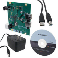
EVB-USB2412
Description
EVALUATION BOARD FOR USB2412
Manufacturer
SMSC
Specifications of EVB-USB2412
Design Resources
EVB-USB2412 Schematic EVB-USB2412 BOM
Main Purpose
Interface, USB 2.0 Hub
Embedded
No
Utilized Ic / Part
USB2421
Primary Attributes
Dual Port Hub, High Speed (480Mbps)
Secondary Attributes
Single 5V Supply
Lead Free Status / RoHS Status
Lead free / RoHS Compliant
Other names
638-1106


Revision 1.0 (02-12-10)
3.3
PIN
21
22
18
28
12
26
11
#
1
3
2
7
8
USBDM_DN[1]
USBDM_DN[2]
USBDP_DN[1]
USBDP_DN[2]
USBDM_UP
USBDP_UP
PRTPWR[1]
PRTPWR[2]
VBUS_DET
OCS_N[1]
OCS_N[2]
SYMBOL
Pin Descriptions (Grouped by Function)
RBIAS
BUFFER
TYPE
I/O12
IO-U
IO-U
IPD
IPU
I-R
DOWNSTREAM USB 2.0 INTERFACES
Table 3.2 USB2412 Pin Descriptions
UPSTREAM USB 2.0 INTERFACES
USB Bus Data
These pins connect to the upstream USB bus data signals (host, port,
or upstream hub).
Detect Upstream VBUS Power
Detects the state of Upstream VBUS power. The SMSC hub monitors
VBUS_DET to determine when to assert the internal D+ pull-up
resistor which signals a connect event.
When designing a detachable hub, this pin should be connected to
VBUS on the upstream port via a 2 to 1 voltage divider.
For self-powered applications with a permanently attached host, this
pin must be connected to 3.3 V.
According to Section 7.2.1 of the USB 2.0 specification, a downstream
port can never provide power to its D+ or D- pull-up resistors unless
the upstream port’s VBUS is in the asserted (powered) state.
The VBUS_DET pin on the hub monitors the state of the upstream
VBUS signal and will not pull-up the D+ resistor if VBUS is not active.
If VBUS goes from an active to an inactive state (Not Powered), the
hub will remove power from the D+ pull-up resistor within 10 seconds.
Hi-Speed USB Data
These pins connect to the downstream USB peripheral devices
attached to the hub’s ports.
USB Power Enable
Enables power to USB peripheral devices that are downstream. The
hub supports active high power controllers only.
Over-Current Sense
Input from external current monitor indicating an over-current
condition. This pin contains an internal pull-up to the 3.3 V supply.
USB Transceiver Bias
A 12.0 kΩ (+/- 1%) resistor is attached from ground to this pin to set
the transceiver’s internal bias settings.
DATASHEET
10
DESCRIPTION
2-Port USB 2.0 Hi-Speed Hub Controller
SMSC USB2412
Datasheet
Related parts for EVB-USB2412
Image
Part Number
Description
Manufacturer
Datasheet
Request
R

Part Number:
Description:
BOARD EVAL FOR USB2514 48-QFN
Manufacturer:
SMSC
Datasheet:

Part Number:
Description:
Networking Modules & Development Tools LAN7500 USB 2.0 BRD 10/100/1000 GigB
Manufacturer:
SMSC
Datasheet:

Part Number:
Description:
BOARD EVAL FOR USB2514/USB2514I
Manufacturer:
SMSC
Datasheet:

Part Number:
Description:
BOARD EVAL FOR USB2512/USB2512I
Manufacturer:
SMSC
Datasheet:

Part Number:
Description:
BOARD EVAL FOR USB2513/USB2513I
Manufacturer:
SMSC
Datasheet:

Part Number:
Description:
BOARD EVALUATION FOR EMC1043
Manufacturer:
SMSC
Datasheet:
Part Number:
Description:
EVALUATION BOARD FOR USB3311C
Manufacturer:
SMSC
Datasheet:
Part Number:
Description:
EVALUATION BOARD FOR USB3317C
Manufacturer:
SMSC
Datasheet:

Part Number:
Description:
EVALUATION BOARD USB2241-AEZG
Manufacturer:
SMSC
Datasheet:

Part Number:
Description:
BOARD EVAL USB2524 SHARE/SWITCH
Manufacturer:
SMSC
Datasheet:

Part Number:
Description:
BOARD EVALUATION FOR USB2502
Manufacturer:
SMSC
Datasheet:
Part Number:
Description:
BOARD EVALUATION FOR USB2504
Manufacturer:
SMSC
Datasheet:

Part Number:
Description:
EVALUATION BOARD LAN9500-ABZJ
Manufacturer:
SMSC
Datasheet:
Part Number:
Description:
Ethernet Modules & Development Tools LAN9500 Design Kit Low-Cost USB Dongle
Manufacturer:
SMSC
Datasheet: