EVB-USB2412 SMSC, EVB-USB2412 Datasheet - Page 11
EVB-USB2412
Manufacturer Part Number
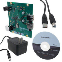
EVB-USB2412
Description
EVALUATION BOARD FOR USB2412
Manufacturer
SMSC
Specifications of EVB-USB2412
Design Resources
EVB-USB2412 Schematic EVB-USB2412 BOM
Main Purpose
Interface, USB 2.0 Hub
Embedded
No
Utilized Ic / Part
USB2421
Primary Attributes
Dual Port Hub, High Speed (480Mbps)
Secondary Attributes
Single 5V Supply
Lead Free Status / RoHS Status
Lead free / RoHS Compliant
Other names
638-1106


2-Port USB 2.0 Hi-Speed Hub Controller
Datasheet
SMSC USB2412
PIN
13
19
16
24
#
NON_REM[1]
NON_REM[0]
SUSP_IND /
SYMBOL
HS_IND
XTALIN
CLKIN
BUFFER
Table 3.2 USB2412 Pin Descriptions (continued)
ICLKx
TYPE
I/O12
I/O
I/O
Non-removable Port Strap Option
This pin will be sampled (in conjunction with SUSP_IND /
NON_REM[0]) at RESET_N negation to determine if ports [2:1]
contain permanently attached (non-removable) devices:
NON_REM[1:0] = ‘00’, all ports are removable.
NON_REM[1:0] = ‘01’, port 1 is non-removable.
NON_REM[1:0] = ‘1x, ports 1 and 2 are non-removable.
Please see
complete description.
Active/Suspend Status LED
Suspend Indicator: Indicates USB hub state. Please see
"LED Strap Option"
NON_REM[0] = ‘0’, SUSP_IND is active high.
NON_REM[0] = ‘1’, SUSP_IND is active low.
‘negated’ = Unconfigured, or configured and in USB Suspend
‘asserted’ = The hub is configured and is active (i.e., not in suspend)
Non-removable Port Strap Option
This pin will be sampled (in conjunction with NON_REM[1]) at
RESET_N negation to determine if ports [2:1] contain permanently
attached (non-removable) devices:
NON_REM[1:0] = ‘00’, all ports are removable.
NON_REM[1:0] = ‘01’, port 1 is non-removable.
NON_REM[1:0] = ‘1x’, ports 1 and 2 are non-removable.
Please see
complete description.
Hi-Speed Upstream Port Indicator
HS_IND: Hi-speed Indicator for upstream port connection speed.
Note:
‘Asserted’ = the hub is connected at HS
‘Negated’ = the hub is connected at FS
24 MHz Crystal Input
This pin connects to either one terminal of the crystal or to an external
24 MHz clock when a crystal is not used.
External Clock Input
This pin connects to either one terminal of the crystal or to an external
24 MHz clock when a crystal is not used.
DATASHEET
An LED can be attached for visual indication. Please see
Section 3.6, "LED Strap Option"
When an LED is not used, this pin requires a 50 kΩ or higher
resistor to ground.
MISC
Section 3.5, "Non-Removable Strap Option"
Section 3.5, "Non-Removable Strap Option"
11
for a complete description.
DESCRIPTION
for a complete description.
Revision 1.0 (02-12-10)
for a
Section 3.6,
for a
Related parts for EVB-USB2412
Image
Part Number
Description
Manufacturer
Datasheet
Request
R

Part Number:
Description:
BOARD EVAL FOR USB2514 48-QFN
Manufacturer:
SMSC
Datasheet:

Part Number:
Description:
Networking Modules & Development Tools LAN7500 USB 2.0 BRD 10/100/1000 GigB
Manufacturer:
SMSC
Datasheet:

Part Number:
Description:
BOARD EVAL FOR USB2514/USB2514I
Manufacturer:
SMSC
Datasheet:

Part Number:
Description:
BOARD EVAL FOR USB2512/USB2512I
Manufacturer:
SMSC
Datasheet:

Part Number:
Description:
BOARD EVAL FOR USB2513/USB2513I
Manufacturer:
SMSC
Datasheet:

Part Number:
Description:
BOARD EVALUATION FOR EMC1043
Manufacturer:
SMSC
Datasheet:
Part Number:
Description:
EVALUATION BOARD FOR USB3311C
Manufacturer:
SMSC
Datasheet:
Part Number:
Description:
EVALUATION BOARD FOR USB3317C
Manufacturer:
SMSC
Datasheet:

Part Number:
Description:
EVALUATION BOARD USB2241-AEZG
Manufacturer:
SMSC
Datasheet:

Part Number:
Description:
BOARD EVAL USB2524 SHARE/SWITCH
Manufacturer:
SMSC
Datasheet:

Part Number:
Description:
BOARD EVALUATION FOR USB2502
Manufacturer:
SMSC
Datasheet:
Part Number:
Description:
BOARD EVALUATION FOR USB2504
Manufacturer:
SMSC
Datasheet:

Part Number:
Description:
EVALUATION BOARD LAN9500-ABZJ
Manufacturer:
SMSC
Datasheet:
Part Number:
Description:
Ethernet Modules & Development Tools LAN9500 Design Kit Low-Cost USB Dongle
Manufacturer:
SMSC
Datasheet: