RDK-249 Power Integrations, RDK-249 Datasheet - Page 25
RDK-249
Manufacturer Part Number
RDK-249
Description
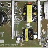
KIT REF DESIGN PFS762HG
Manufacturer
Power Integrations
Series
HiperTFS®r
Specifications of RDK-249
Main Purpose
Reference Design, PC Power Supply
Embedded
No
Utilized Ic / Part
TFS762HG
Primary Attributes
12V 25A, 5V 2.9A Outputs, 300 ~ 385 VDC Input
Output Voltage
5 V
Input / Supply Voltage (max)
385 VDC
Input / Supply Voltage (min)
300 VDC
Duty Cycle (max)
50 %
Mounting Style
Through Hole
Output Current
2.9 A
Output Power
14.5 W
Lead Free Status / RoHS Status
Lead free / RoHS Compliant
Secondary Attributes
-
Other names
596-1398


Page 25 of 48
n
Z
tC
ENTER HiperTFS STANDBY VARIABLES
Select Current Limit
ILIM_MIN
ILIM_TYP
ILIM_MAX
R(EN)
fSmin
I^2fmin
VOR
VDS
VD_SB
KP
KP_TRANSIENT
ENTER BIAS WINDING VARIABLES
VB
IB
PB
VDB
NB
VZOV
UVLO VARIABLES
RLS
V_UV_ACTUAL
ENTER TRANSFORMER CORE/CONSTRUCTION VARIABLES
Core Type
Core
Bobbin
AE
LE
AL
BW
M
L
NS_SB
DC INPUT VOLTAGE PARAMETERS
VMIN_SB
VMAX_SB
CURRENT WAVEFORM SHAPE PARAMETERS
DMAX_SB
IAVG
IP_SB
IR_SB
IRMS_SB
TRANSFORMER PRIMARY DESIGN PARAMETERS
LP_SB
90.00
EE25
0.70
0.50
3.00
STD
EE25
EE25_BOBBIN
124000
115.65
374.77
841.65
0.605
0.650
0.696
280.0
50.19
16.00
20.00
22.00
0.404
EE25
1420
Standard Current Limit
0.71
0.36
0.32
0.70
9.11
4.00
7.34
10.2
0.46
0.20
0.60
0.43
0.32
102
0.5
90
10
0
2
3
Tel: +1 408 414 9200 Fax: +1 408 414 9201
M-Ohms
A^2kHz
k-ohms
nH/T^2
cm^2
P/N:
P/N:
mm
mm
mA
ms
cm
uH
Hz
W
V
V
A
A
A
V
V
V
V
V
V
V
A
A
A
A
Efficiency Estimate at output terminals.
Under 0.7 if no better data available
Z Factor. Ratio of secondary side losses to
the total losses in the power supply. Use 0.5
if no better data available
Bridge Rectifier Conduction Time Estimate
Enter "LOW" for low current limit, "RED" for
reduced current limit (sealed adapters),
"STD" for standard current limit or "INC" for
increased current limit (peak or higher power
applications)
Minimum Current Limit
Typical Current Limit
Maximum Current Limit
Enable pin resistor
Minimum Device Switching Frequency
I^2f (product of current limit squared and
frequency is trimmed for tighter tolerance)
Reflected Output Voltage (VOR < 135 V
Recommended)
HiperTFS Standby On State Drain to Source
Voltage
Output Winding Diode Forward Voltage Drop
Ripple to Peak Current Ratio (KP < 6)
Transient Ripple to Peak Current Ratio.
Ensure KP_TRANSIENT > 0.25
Bias Winding Voltage
Bias winding Load current
Bias winidng power
Bias Winding Diode Forward Voltage Drop
Bias Winding Number of Turns
Over Voltage Protection zener diode voltage.
Line sense resistor (from Main converter
section)
Typical DC start-up voltage
Enter Transformer Core
PC40EE25-Z
EE25_BOBBIN
Core Effective Cross Sectional Area
Core Effective Path Length
Ungapped Core Effective Inductance
Bobbin Physical Winding Width
Safety Margin Width (Half the Primary to
Secondary Creepage Distance)
Number of Primary Layers
Number of Secondary Turns
Minimum DC Input Voltage
Maximum DC Input Voltage
Duty Ratio at full load, minimum primary
inductance and minimum input voltage
Average Primary Current
Minimum Peak Primary Current
Primary Ripple Current
Primary RMS Current
Typical Primary Inductance. +/- 10% to
ensure a minimum primary inductance of 765
uH
Power Integrations
www.powerint.com
Related parts for RDK-249
Image
Part Number
Description
Manufacturer
Datasheet
Request
R

Part Number:
Description:
KIT REF DESIGN TOP HX FOR TOP258
Manufacturer:
Power Integrations
Datasheet:

Part Number:
Description:
KIT REF DESIGN LINKSWITCH 2
Manufacturer:
Power Integrations
Datasheet:

Part Number:
Description:
KIT REF DESIGN 1.2W PS TN FAMILY
Manufacturer:
Power Integrations
Datasheet:

Part Number:
Description:
KIT REF DESIGN 36-72W MOTOR DRVR
Manufacturer:
Power Integrations
Datasheet:

Part Number:
Description:
KIT REF DESIGN FOR LNK457D
Manufacturer:
Power Integrations
Datasheet:

Part Number:
Description:
REFERENCE DESIGN LINKSWITCH-PH
Manufacturer:
Power Integrations
Datasheet:

Part Number:
Description:
Specifications: Manufacturer: Power Integrations ; Output Voltage: 380 VDC ; Input / Supply Voltage (Max): 264 VAC ; Input / Supply Voltage (Min): 90 VAC ; Mounting Style: Through Hole ; Output Current: 0.913 A ; Output Power: 347 W
Manufacturer:
Power Integrations, Inc.

Part Number:
Description:
Power Management Modules & Development Tools TOPSwitch-JX REF. DESIGN KIT
Manufacturer:
Power Integrations
Datasheet:
Part Number:
Description:
Power Management IC Development Tools REF DESIGN RDR-292 PFF LED STREET LIGHT
Manufacturer:
Power Integrations

Part Number:
Description:
KIT REF DESIGN FOR LNK403EG
Manufacturer:
Power Integrations
Datasheet:

Part Number:
Description:
KIT REF DESIGN FOR LNK406EG
Manufacturer:
Power Integrations
Datasheet:

Part Number:
Description:
KIT REF DESIGN DG CAPZERO
Manufacturer:
Power Integrations
Datasheet:

Part Number:
Description:
KIT REF DESIGN LINKSWITCH-CV
Manufacturer:
Power Integrations
Datasheet:
Part Number:
Description:
Specifications: Family: Eval Boards - DC/DC & AC/DC (Off-Line) SMPS ; Series: HiperLCS™ ; Main Purpose: DC/DC, Step Down ; Outputs and Type: 1, Isolated ; Power - Output: 150W ; Voltage - Output: 24V ; Current - Output: 6.25A ; Voltage - Input:
Manufacturer:
Power Integrations, Inc.
Datasheet:

Part Number:
Description:
KIT REFERENCE DESIGN W/TN376PN
Manufacturer:
Power Integrations
Datasheet: