PIC16F721-I/ML Microchip Technology, PIC16F721-I/ML Datasheet - Page 7
PIC16F721-I/ML
Manufacturer Part Number
PIC16F721-I/ML
Description
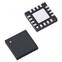
MCU PIC 4K FLASH 20-QFN
Manufacturer
Microchip Technology
Series
PIC® XLP™ 16Fr
Datasheets
1.PIC16F722-ISS.pdf
(8 pages)
2.PIC16LF720-ISS.pdf
(244 pages)
3.PIC16F720-ISO.pdf
(36 pages)
4.PIC16F720-ISO.pdf
(8 pages)
5.PIC16F721-IML.pdf
(6 pages)
Specifications of PIC16F721-I/ML
Core Size
8-Bit
Program Memory Size
7KB (4K x 14)
Peripherals
Brown-out Detect/Reset, POR, PWM, WDT
Core Processor
PIC
Speed
16MHz
Connectivity
I²C, SPI, UART/USART
Number Of I /o
17
Program Memory Type
FLASH
Ram Size
256 x 8
Voltage - Supply (vcc/vdd)
1.8 V ~ 5.5 V
Data Converters
A/D 12x8b
Oscillator Type
Internal
Operating Temperature
-40°C ~ 85°C
Package / Case
20-VFQFN Exposed Pad
Controller Family/series
PIC16F
No. Of I/o's
18
Ram Memory Size
256Byte
Cpu Speed
16MHz
No. Of Timers
3
Lead Free Status / RoHS Status
Lead free / RoHS Compliant
Eeprom Size
-
Lead Free Status / RoHS Status
Lead free / RoHS Compliant


REGISTER 3-2:
2011 Microchip Technology Inc.
bit 13
bit 6
Legend:
R = Readable bit
-n = Value for blank device
bit 13
bit 12
bit 11-10 Unimplemented: Read as ‘1’
bit 9-8
bit 7
bit 6
bit 5
bit 4
bit 3
bit 2
bit 1-0
Note 1: Debug bit is ignored when code-protect is enabled (CP= 0).
DEBUG
R/P-1
R/P-1
CP
2: Fixed Voltage Reference is automatically enabled whenever the BOR is enabled.
DEBUG
0 = Background debugger is enabled
1 = Background debugger is disabled
PLLEN: INTOSC PLL Enable bit
0 = INTOSC Frequency is 500 kHz
1 = INTOSC Frequency is 16 MHz (32x)
BOREN<1:0>: Brown-out Reset Enable bits
0x = Brown-out Reset disabled (Preconditioned State)
10 = Brown-out Reset enabled during operation and disabled in Sleep
11 = Brown-out Reset enabled
Unimplemented: Read as ‘1’
CP: Flash Program Memory Code Protection bit
PIC16F720/721
0 = 0000h to 07FFh/0FFFh code protection on
1 = Code protection off
MCLRE: RA3/MCLR/V
1 = RA3/MCLR/V
0 = RA3/MCLR/V
PWRTE: Power-up Timer Enable bit
0 = PWRT enabled
1 = PWRT disabled
WDTEN: Watchdog Timer Enable bit
0 = WDT disabled
1 = WDT enabled
Unimplemented: Read as ‘1’
FOSC<1:0>: Oscillator Selection bits
11 = EC oscillator: CLKO function on RA4/CLKO pin, CLKI on RA5/CLKI
10 = EC oscillator: I/O function on RA4/CLKO pin, CLKI on RA5/CLKI
01 = INTOSC oscillator: CLKO function on RA4/CLKO pin, I/O function on RA5/CLKI
00 = INTOSCIO oscillator: I/O function on RA4/CLKO pin, I/O function on RA5/CLKI
( 1)
(1)
: Debugger Mode bit
MCLRE
PLLEN
R/P-1
CONFIGURATION WORD 1
R/P-1
PP
PP
pin function is MCLR; Weak pull-up enabled.
pin function is digital input; MCLR internally disabled; Weak pull-up disabled
PP
W = Writable bit
1 = Bit is set
U = Unimplemented bit, read as ‘1’
Pin Function Select bit
PWRTE
R/P-1
U-1
—
Advance Information
WDTEN
(2)
R/P-1
U-1
—
BOREN1
PIC16(L)F720/721
R/P-0
U-1
—
0 = Bit is cleared
x = Bit is unknown
BOREN0
FOSC1
R/P-0
R/P-1
DS41409B-page 7
FOSC0
R/P-1
U-1
—
bit 7
bit 0
Related parts for PIC16F721-I/ML
Image
Part Number
Description
Manufacturer
Datasheet
Request
R

Part Number:
Description:
MCU PIC 4K FLASH 20-SOIC
Manufacturer:
Microchip Technology
Datasheet:

Part Number:
Description:
MCU PIC 4K FLASH 20-SSOP
Manufacturer:
Microchip Technology
Datasheet:

Part Number:
Description:
MCU PIC 4K FLASH 20-DIP
Manufacturer:
Microchip Technology
Datasheet:

Part Number:
Description:
7 KB FLASH, 256 B SRAM, 18 I/O 20 QFN 4x4mm TUBE
Manufacturer:
Microchip Technology
Datasheet:
Part Number:
Description:
7 KB FLASH, 256 B SRAM, 18 I/O 20 PDIP .300in TUBE
Manufacturer:
Microchip Technology
Datasheet:
Part Number:
Description:
7 KB FLASH, 256 B SRAM, 18 I/O 20 SOIC .300in TUBE
Manufacturer:
Microchip Technology
Datasheet:
Part Number:
Description:
7 KB FLASH, 256 B SRAM, 18 I/O 20 SSOP .209in TUBE
Manufacturer:
Microchip Technology
Datasheet:

Part Number:
Description:
IC PIC MCU FLASH 2KX14 28-QFN
Manufacturer:
Microchip Technology
Datasheet:

Part Number:
Description:
IC PIC MCU FLASH 2KX14 28-SOIC
Manufacturer:
Microchip Technology
Datasheet:

Part Number:
Description:
IC PIC MCU FLASH 2KX14 28DIP
Manufacturer:
Microchip Technology
Datasheet:
Part Number:
Description:
IC PIC MCU FLASH 2KX14 28-SOIC
Manufacturer:
Microchip Technology
Datasheet:
Part Number:
Description:
IC PIC MCU FLASH 2KX14 28QFN
Manufacturer:
Microchip Technology

Part Number:
Description:
IC PIC MCU FLASH 2KX14 28SSOP
Manufacturer:
Microchip Technology
Part Number:
Description:
IC PIC MCU FLASH 2KX14 8-SSOP
Manufacturer:
Microchip Technology
Datasheet:
Part Number:
Description:
IC PIC MCU FLASH 2KX14 28-SSOP
Manufacturer:
Microchip Technology
Datasheet: