TWR-S08MM128-KIT Freescale Semiconductor, TWR-S08MM128-KIT Datasheet - Page 34
TWR-S08MM128-KIT
Manufacturer Part Number
TWR-S08MM128-KIT
Description
MCU, MPU & DSP Development Tools For 9S08MM128 USB CAN
Manufacturer
Freescale Semiconductor
Datasheet
1.MC9S08MM128CMB.pdf
(52 pages)
Specifications of TWR-S08MM128-KIT
Processor To Be Evaluated
9S08MM128
Data Bus Width
8 bit
Interface Type
USB, CAN
Silicon Manufacturer
Freescale
Core Architecture
Coldfire, HCS08
Core Sub-architecture
Coldfire V1, HCS08
Silicon Core Number
MCF51, MC9S08
Silicon Family Name
Flexis - MCF51MM, Flexis - S08MM
Rohs Compliant
Yes
Lead Free Status / RoHS Status
Lead free / RoHS Compliant


Electrical Characteristics
3
4
5
6
7
34
#
1
2
3
4
5
This specification applies to any time the PLL VCO divider or reference divider is changed, or changing from PLL
disabled (BLPE, BLPI) to PLL enabled (PBE, PEE). If a crystal/resonator is being used as the reference, this
specification assumes it is already running.
Jitter is the average deviation from the programmed frequency measured over the specified interval at maximum f
Measurements are made with the device powered by filtered supplies and clocked by a stable external clock signal.
Noise injected into the FLL circuitry via V
percentage for a given interval.
625 ns represents 5 time quanta for CAN applications, under worst-case conditions of 8 MHz CAN bus clock, 1 Mbps
CAN Bus speed, and 8 time quanta per bit for bit time settings. 5 time quanta is the minimum time between a
synchronization edge and the sample point of a bit using 8 time quanta per bit.
Below D
if the MCG is already in lock, then the MCG may stay in lock.
Below D
lock.
Freescale reserves the right to change the detail specifications as may be required to permit improvements in the design of its products.
Oscillator crystal or resonator
(EREFS = 1, ERCLKEN = 1)
Load capacitors
Feedback resistor
Series resistor — Low range
Series resistor — High range
unl
lock
minimum, the MCG will not exit lock if already in lock. Above D
minimum, the MCG is guaranteed to enter lock. Above D
Table 19. XOSC (Temperature Range = –40 to 105
Characteristic
• Low range (RANGE = 0)
• High range (RANGE = 1),
• FEE or FBE mode
• High range (RANGE = 1),
• PEE or PBE mode
• High range (RANGE = 1),
• High gain (HGO = 1),
• BLPE mode
• High range (RANGE = 1),
• Low power (HGO = 0),
• BLPE mode
• Low range
• High range
• Low Gain (HGO = 0)
• High Gain (HGO = 1)
• Low Gain (HGO = 0)
• High Gain (HGO = 1)
(32 kHz to 38.4 kHz)
(1 MHz to 16 MHz)
DD
and V
8 MHz
4 MHz
1 MHz
SS
and variation in crystal oscillator frequency increase the C
2
3
lock
Symbol
f
unl
f
maximum, the MCG will not enter lock. But
hi-hgo
f
f
hi-pll
hi-fll
hi-lp
R
R
R
C
C
—
f
lo
maximum, the MCG is guaranteed to exit
1
2
F
S
S
See crystal or resonator manufacturer’s
Min
°
32
—
—
—
—
—
—
—
—
C Ambient)
1
1
1
1
recommendation.
Typ
100
10
—
—
—
—
—
1
0
0
0
0
0
1
Freescale Semiconductor
Max
38.4
16
16
10
20
—
—
—
—
—
5
8
0
BUS
Jitter
MHz
MHz
MHz
MHz
Unit
kHz
M
k
k
.
C
D
D
D
D
D
D
D
D
D
D
D
D
D
D
D
Related parts for TWR-S08MM128-KIT
Image
Part Number
Description
Manufacturer
Datasheet
Request
R

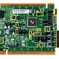
Part Number:
Description:
TOWER SYSTEM BOARD MC9S08MM128
Manufacturer:
Freescale Semiconductor
Datasheet:

Part Number:
Description:
Development Boards & Kits - S08 / S12 S08PT60 Tower Kit
Manufacturer:
Freescale Semiconductor
Datasheet:
Part Number:
Description:
Development Boards & Kits - S08 / S12 S08PT60Tower MCU mod
Manufacturer:
Freescale Semiconductor
Datasheet:
Part Number:
Description:
TOWER UNIVERSAL RS08/S08
Manufacturer:
Freescale Semiconductor
Datasheet:

Part Number:
Description:
Manufacturer:
Freescale Semiconductor, Inc
Datasheet:
Part Number:
Description:
Manufacturer:
Freescale Semiconductor, Inc
Datasheet:
Part Number:
Description:
Manufacturer:
Freescale Semiconductor, Inc
Datasheet:
Part Number:
Description:
Manufacturer:
Freescale Semiconductor, Inc
Datasheet:
Part Number:
Description:
Manufacturer:
Freescale Semiconductor, Inc
Datasheet:
Part Number:
Description:
Manufacturer:
Freescale Semiconductor, Inc
Datasheet:
Part Number:
Description:
Manufacturer:
Freescale Semiconductor, Inc
Datasheet:
Part Number:
Description:
Manufacturer:
Freescale Semiconductor, Inc
Datasheet:
Part Number:
Description:
Manufacturer:
Freescale Semiconductor, Inc
Datasheet:
Part Number:
Description:
Manufacturer:
Freescale Semiconductor, Inc
Datasheet:
Part Number:
Description:
Manufacturer:
Freescale Semiconductor, Inc
Datasheet: