TWR-S08MM128-KIT Freescale Semiconductor, TWR-S08MM128-KIT Datasheet - Page 15
TWR-S08MM128-KIT
Manufacturer Part Number
TWR-S08MM128-KIT
Description
MCU, MPU & DSP Development Tools For 9S08MM128 USB CAN
Manufacturer
Freescale Semiconductor
Datasheet
1.MC9S08MM128CMB.pdf
(52 pages)
Specifications of TWR-S08MM128-KIT
Processor To Be Evaluated
9S08MM128
Data Bus Width
8 bit
Interface Type
USB, CAN
Silicon Manufacturer
Freescale
Core Architecture
Coldfire, HCS08
Core Sub-architecture
Coldfire V1, HCS08
Silicon Core Number
MCF51, MC9S08
Silicon Family Name
Flexis - MCF51MM, Flexis - S08MM
Rohs Compliant
Yes
Lead Free Status / RoHS Status
Lead free / RoHS Compliant


2.3
This section provides information about operating temperature range, power dissipation, and package thermal resistance. Power
dissipation on I/O pins is usually small compared to the power dissipation in on-chip logic and it is user-determined rather than
being controlled by the MCU design. In order to take P
actual pin voltage and V
(heavy loads), the difference between pin voltage and V
The average chip-junction temperature (T
where:
Freescale Semiconductor
Freescale reserves the right to change the detail specifications as may be required to permit improvements in the design of its products.
1
2
3
4
T
P
P
P
Junction temperature is a function of die size, on-chip power dissipation, package thermal resistance, mounting
site (board) temperature, ambient temperature, air flow, power dissipation of other components on the board, and
board thermal resistance.
Junction to Ambient Natural Convection
1s — Single layer board, one signal layer
2s2p — Four layer board, 2 signal and 2 power layers
A
JA
D
int
I/O
Thermal Characteristics
#
1
2
3
4
= Ambient temperature, C
= P
= Package thermal resistance, junction-to-ambient, C/W
= I
= Power dissipation on input and output pins — user determined
int
DD
P
V
Symbol
T
SS
I/O
JMAX
T
DD
JA
JA
or V
A
, Watts — chip internal power
DD
and multiply by the pin current for each I/O pin. Except in cases of unusually high pin current
Operating temperature range (packaged):
Maximum junction temperature
Thermal resistance
Thermal resistance
J
) in C can be obtained from:
Table 6. Thermal Characteristics
T
J
= T
I/O
A
1,2,3,4
1, 2, 3, 4
SS
+ (P
into account in power calculations, determine the difference between
Rating
or V
MC9S08MM128
MC9S08MM64
MC9S08MM32
MC9S08MM32A
81-pin MBGA
80-pin LQFP
64-pin LQFP
81-pin MBGA
80-pin LQFP
64-pin LQFP
D
Single-layer board — 1s
Four-layer board — 2s2p
DD
will be very small.
JA
)
–40 to 105
–40 to 105
–40 to 105
–40 to 105
Value
135
77
55
68
47
40
49
Electrical Characteristics
C/W
C/W
Unit
C
C
Eqn. 1
15
Related parts for TWR-S08MM128-KIT
Image
Part Number
Description
Manufacturer
Datasheet
Request
R

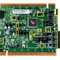
Part Number:
Description:
TOWER SYSTEM BOARD MC9S08MM128
Manufacturer:
Freescale Semiconductor
Datasheet:

Part Number:
Description:
Development Boards & Kits - S08 / S12 S08PT60 Tower Kit
Manufacturer:
Freescale Semiconductor
Datasheet:
Part Number:
Description:
Development Boards & Kits - S08 / S12 S08PT60Tower MCU mod
Manufacturer:
Freescale Semiconductor
Datasheet:
Part Number:
Description:
TOWER UNIVERSAL RS08/S08
Manufacturer:
Freescale Semiconductor
Datasheet:

Part Number:
Description:
Manufacturer:
Freescale Semiconductor, Inc
Datasheet:
Part Number:
Description:
Manufacturer:
Freescale Semiconductor, Inc
Datasheet:
Part Number:
Description:
Manufacturer:
Freescale Semiconductor, Inc
Datasheet:
Part Number:
Description:
Manufacturer:
Freescale Semiconductor, Inc
Datasheet:
Part Number:
Description:
Manufacturer:
Freescale Semiconductor, Inc
Datasheet:
Part Number:
Description:
Manufacturer:
Freescale Semiconductor, Inc
Datasheet:
Part Number:
Description:
Manufacturer:
Freescale Semiconductor, Inc
Datasheet:
Part Number:
Description:
Manufacturer:
Freescale Semiconductor, Inc
Datasheet:
Part Number:
Description:
Manufacturer:
Freescale Semiconductor, Inc
Datasheet:
Part Number:
Description:
Manufacturer:
Freescale Semiconductor, Inc
Datasheet:
Part Number:
Description:
Manufacturer:
Freescale Semiconductor, Inc
Datasheet: