LPC-P2919 Olimex Ltd., LPC-P2919 Datasheet - Page 4
LPC-P2919
Manufacturer Part Number
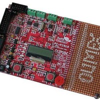
LPC-P2919
Description
MCU, MPU & DSP Development Tools DEV BRD FOR LPC2919 768KB FLASH 56KBSRAM
Manufacturer
Olimex Ltd.
Datasheet
1.LPC-P2919.pdf
(21 pages)
Specifications of LPC-P2919
Processor To Be Evaluated
LPC2919 ARM968E-S
Data Bus Width
16 bit, 32 bit
Interface Type
RS-232, CAN, SPI
Dimensions
140 mm x 89 mm
Operating Supply Voltage
9 V
Lead Free Status / RoHS Status
Lead free / RoHS Compliant


–
–
–
–
–
–
–
–
–
–
–
Two 8-channel 10-bit ADCs provide a total 16 analog inputs, with conversion
times as low as 2.44 μs per channel. Each channel provides a compare function
to minimize interrupts.
24 level-sensitive external interrupt pins, including CAN and LIN wake- up
features.
External Static Memory Controller (SMC) with eight memory banks; up to 32-
bit data bus; up to 24-bit address bus.
Processor wake-up from power-down via external interrupt pins; CAN or LIN
activity.
Flexible Reset Generator Unit (RGU) able to control resets of individual
modules.
Flexible Clock-Generation Unit (CGU) able to control clock frequency of
individual modules.
Highly configurable system Power Management Unit (PMU).
Standard ARM test and debug interface with real-time in-circuit emulator.
Boundary-scan test supported.
Dual power supply:
−40 °C to 85 °C ambient operating temperature range.
–
–
–
–
–
–
–
–
–
On-chip very low-power ring oscillator; fixed frequency of 0.4 MHz;
always on to provide a Safe_Clock source for system monitoring.
On-chip crystal oscillator with operating range from 10 MHz to 50 MHz
- max. PLL input 15 MHz.
On-chip PLL allows CPU operation up to a maximum CPU rate of 80
MHz.
Generation of up to 10 base clocks.
Seven fractional dividers.
clock control of individual modules.
allows minimization of system operating power consumption in any
configuration.
CPU operating voltage: 1.8 V ± 5%.
I/O operating voltage: 2.7 V to 3.6 V; inputs tolerant up to 5.5 V.
Page 4
Related parts for LPC-P2919
Image
Part Number
Description
Manufacturer
Datasheet
Request
R

Part Number:
Description:
MCU, MPU & DSP Development Tools DEV BRD FOR LPC2378 512KB FLASH 16KB RAM
Manufacturer:
Olimex Ltd.

Part Number:
Description:
MCU, MPU & DSP Development Tools HDR BRD FOR LPC2294 1MB SRAM 4MB FLASH
Manufacturer:
Olimex Ltd.

Part Number:
Description:
MCU, MPU & DSP Development Tools DEV BRD FOR LPC2294 256KB FLASH 16KB RAM
Manufacturer:
Olimex Ltd.
Datasheet:
Part Number:
Description:
MCU, MPU & DSP Development Tools DEV BRD FOR LPC2294 256KB FLASH 16KB RAM
Manufacturer:
Olimex Ltd.
Datasheet:

Part Number:
Description:
MCU, MPU & DSP Development Tools PROTOTYPE BOARD FOR LPC2129
Manufacturer:
Olimex Ltd.

Part Number:
Description:
MCU, MPU & DSP Development Tools PROTOTYPE BRD FOR LPC2138 6V 2-CH
Manufacturer:
Olimex Ltd.

Part Number:
Description:
MCU, MPU & DSP Development Tools DEV BRD FOR LPC2294 256KB FLASH 16KB RAM
Manufacturer:
Olimex Ltd.
Datasheet:

Part Number:
Description:
MCU, MPU & DSP Development Tools PROTOTYPE BRD FOR LPC2148 6V 2-CH
Manufacturer:
Olimex Ltd.
Datasheet:

Part Number:
Description:
MCU, MPU & DSP Development Tools DEV BRD FOR LPC2468 128MBFLASH 16MBSDRAM
Manufacturer:
Olimex Ltd.
Datasheet:
Part Number:
Description:
MCU, MPU & DSP Development Tools DEV BRD FOR LPC2294 256KB FLASH 16KB RAM
Manufacturer:
Olimex Ltd.
Datasheet:

Part Number:
Description:
Microcontroller & Microprocessor Development Tools HDR BRD FOR LPC3131
Manufacturer:
Olimex Ltd.
Datasheet:

Part Number:
Description:
Microcontroller & Microprocessor Development Tools TCP-IP DEV BRD PIC32MX460F512
Manufacturer:
Olimex Ltd.
Datasheet:

Part Number:
Description:
Microcontroller & Microprocessor Development Tools PROTOTYPE BOARD TMS320F28027
Manufacturer:
Olimex Ltd.
Datasheet:

Part Number:
Description:
Microcontroller & Microprocessor Development Tools MP3 PLYR MOD WITH VS1002
Manufacturer:
Olimex Ltd.
Datasheet:
Part Number:
Description:
Microcontroller & Microprocessor Development Tools MP3 PLYR MOD BAT WITH VS1002
Manufacturer:
Olimex Ltd.
Datasheet: