EVAL-IBU-STR7 STMicroelectronics, EVAL-IBU-STR7 Datasheet - Page 26
EVAL-IBU-STR7
Manufacturer Part Number
EVAL-IBU-STR7
Description
Power Management Modules & Development Tools L640 SPI DC Driver Multi-Motor Eval BRD
Manufacturer
STMicroelectronics
Type
Motor / Motion Controllers & Driversr
Datasheet
1.EVAL-IBU-STR7.pdf
(34 pages)
Specifications of EVAL-IBU-STR7
Interface Type
RS-232, Ethernet
Operating Supply Voltage
4.4 V to 36 V
Product
Power Management Modules
For Use With/related Products
L6460
Lead Free Status / RoHS Status
Lead free / RoHS Compliant
Available stocks
Company
Part Number
Manufacturer
Quantity
Price


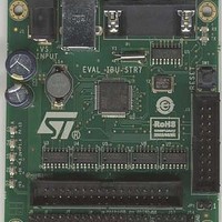
The EVAL6460 controlled by the EVAL_IBU-STR7
3.2.7
3.2.8
26/34
Figure 28. Interrupt controller diagram
Here you can choose the events that can cause an interrupt signal.
How to put the device into "low power" condition and awaken it
When in normal operating mode, the microcontroller can place the L6460 in "low power
mode". In this condition the L6460 sets all bridge outputs in high impedance, powers down
all regulators (including system regulators and charge pump) and disables almost all its
circuits, including the internal clock, reducing power consumption as much as possible.
In the first software window click the L6460 device and then the "Supervisory and Reset
Manager" button, the window in
Push the "Set Low Power mode" button in the middle of the window, the L6460 enters into
low power mode status (refer to datasheet section - low power mode).
To awaken the device push the "Awake neg. pulse" button in the bottom right-hand side, the
L6460 then exits from low power mode.
How to generate a PWM
The L6460 includes three general purpose PWM generators that can be redirected on GPIO
pins. Aux_PWM_1 and Aux_PWM_2 work with a fixed period F
programmable duty cycle; Aux_PWM_3 has a programmable base time and a
programmable time for both high and low levels.
In the first software window click the L6460 device, in the block diagram it is possible to set
the PWM characteristics by pushing the relative button.
If you want to extend the PWM on the GPIO pin you have to also set the GPIO configuration.
For example to set the Aux_PWM_1 on GPIO11 configure the GPIO as in
the Aux_PWM_1 button and move the slider to obtain the desired duty cycle. You can
measure the PWM generated on the GPIO11 pin of the J11 connector.
Doc ID 16599 Rev 2
Figure 27
appears.
OSC
/2 and have a
Figure
29, click
AN3097
Related parts for EVAL-IBU-STR7
Image
Part Number
Description
Manufacturer
Datasheet
Request
R

Part Number:
Description:
ENERCHIP CC EVAL KIT
Manufacturer:
Cymbet Corporation
Datasheet:

Part Number:
Description:
BOARD EVAL FOR AD976
Manufacturer:
Analog Devices Inc
Datasheet:

Part Number:
Description:
BOARD EVAL FOR ADXL345
Manufacturer:
Analog Devices Inc
Datasheet:

Part Number:
Description:
ENERCHIP CC SEH EVAL KIT
Manufacturer:
Cymbet Corporation
Datasheet:

Part Number:
Description:
ENERCHIP EP ENERGY HARVEST EVAL
Manufacturer:
Cymbet Corporation
Datasheet:

Part Number:
Description:
EVAL BOARD FOR TW6864-LB2-GR
Manufacturer:
Intersil
Datasheet:
Part Number:
Description:
EVAL BOARD FOR TW8816-LB3-GR
Manufacturer:
Intersil
Datasheet:
Part Number:
Description:
EVAL BOARD FOR TW8817-TA3-GRS
Manufacturer:
Intersil
Datasheet:

Part Number:
Description:
EVALUATION MODULE FOR ADUM4160
Manufacturer:
Analog Devices Inc
Datasheet:

Part Number:
Description:
BOARD EVALUATION ADCMP581BCP
Manufacturer:
Analog Devices Inc
Datasheet:
Part Number:
Description:
BOARD EVALUATION ADM1041
Manufacturer:
Analog Devices Inc
Datasheet:

Part Number:
Description:
EVAL BOARD FOR STM32F107VCT
Manufacturer:
STMicroelectronics
Datasheet:
Part Number:
Description:
BOARD EVAL FOR AD1954
Manufacturer:
Analog Devices Inc
Datasheet:
Part Number:
Description:
BOARD EVAL FOR AD1955
Manufacturer:
Analog Devices Inc
Datasheet:

Part Number:
Description:
BOARD EVAL FOR AD7655
Manufacturer:
Analog Devices Inc
Datasheet: