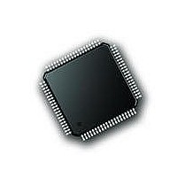
PIC18F86J72-I/PT Microchip Technology, PIC18F86J72-I/PT Datasheet - Page 471

PIC18F86J72-I/PT
Manufacturer Part Number
PIC18F86J72-I/PT
Description
IC PIC MCU 8BIT 14KB FLSH 80TQFP
Manufacturer
Microchip Technology
Series
PIC® 18Fr
Datasheet
1.PIC18F86J72-IPT.pdf
(480 pages)
Specifications of PIC18F86J72-I/PT
Program Memory Type
FLASH
Program Memory Size
64KB (32K x 16)
Package / Case
80-TQFP
Core Processor
PIC
Core Size
8-Bit
Speed
48MHz
Connectivity
I²C, LIN, SPI, UART/USART
Peripherals
Brown-out Detect/Reset, LCD, LVD, POR, PWM, WDT
Number Of I /o
51
Ram Size
3.8K x 8
Voltage - Supply (vcc/vdd)
2 V ~ 3.6 V
Data Converters
A/D 12x12b
Oscillator Type
Internal
Operating Temperature
-40°C ~ 85°C
Data Bus Width
8 bit
Data Ram Size
4 KB
Interface Type
SPI, USART, SPI, I2C
Maximum Clock Frequency
8 MHz
Number Of Programmable I/os
51
Number Of Timers
4
Operating Supply Voltage
2 V to 3.6 V
Maximum Operating Temperature
+ 85 C
Mounting Style
SMD/SMT
Minimum Operating Temperature
- 40 C
On-chip Adc
14
Controller Family/series
PIC18F
No. Of I/o's
51
Ram Memory Size
3923Byte
Cpu Speed
12MIPS
No. Of Timers
4
Rohs Compliant
Yes
Lead Free Status / RoHS Status
Lead free / RoHS Compliant
Lead Free Status / RoHS Status
Lead free / RoHS Compliant, Lead free / RoHS Compliant
Available stocks
Company
Part Number
Manufacturer
Quantity
Price
Company:
Part Number:
PIC18F86J72-I/PT
Manufacturer:
Microchip Technology
Quantity:
10 000
- Current page: 471 of 480
- Download datasheet (5Mb)
Pinout I/O Descriptions ....................................................... 13
PLL...................................................................................... 30
POP .................................................................................. 363
POR. See Power-on Reset.
PORTA
PORTB
PORTC
PORTD
PORTE
PORTF
PORTG
Power-Managed Modes ...................................................... 35
2010 Microchip Technology Inc.
RF7/AN5/SS/SEG25................................................... 18
RG0/LCDBIAS0 .......................................................... 19
RG1/TX2/CK2 ............................................................. 19
RG2/RX2/DT2/V
RG3/V
RG4/SEG26/RTCC ..................................................... 19
SAV
SAV
SCKA .......................................................................... 20
SDIA............................................................................ 20
SDOA.......................................................................... 20
SV
SV
V
V
V
HSPLL and ECPLL Oscillator Modes ......................... 30
Use with INTOSC........................................................ 30
Associated Registers ................................................ 107
LATA Register........................................................... 106
PORTA Register ....................................................... 106
TRISA Register ......................................................... 106
Associated Registers ................................................ 110
LATB Register........................................................... 108
PORTB Register ....................................................... 108
RB7:RB4 Interrupt-on-Change Flag (RBIF Bit)......... 108
TRISB Register ......................................................... 108
Associated Registers ................................................ 113
LATC Register .......................................................... 111
PORTC Register ....................................................... 111
RC3/SCK/SCL/SEG17 Pin........................................ 211
TRISC Register......................................................... 111
Associated Registers ................................................ 115
LATD Register .......................................................... 114
PORTD Register ....................................................... 114
TRISD Register......................................................... 114
Associated Registers ................................................ 117
LATE Register........................................................... 116
PORTE Register ....................................................... 116
TRISE Register ......................................................... 116
Associated Registers ................................................ 120
LATF Register........................................................... 118
PORTF Register ....................................................... 118
TRISF Register ......................................................... 118
Associated Registers ................................................ 122
LATG Register .......................................................... 121
PORTG Register....................................................... 121
TRISG Register......................................................... 121
and SPI Operation .................................................... 203
Clock Sources............................................................. 35
Clock Transitions and Status Indicators...................... 36
Entering....................................................................... 35
Exiting Idle and Sleep Modes ..................................... 41
DD
DDCORE
SS
DD
SS
.............................................................................. 19
DD
SS
............................................................................. 19
........................................................................... 20
........................................................................... 20
LCAP
......................................................................... 20
......................................................................... 20
/V
2................................................................ 19
CAP
............................................................ 19
LCAP
1................................................ 19
Preliminary
PIC18F87J72 FAMILY
Power-on Reset (POR)....................................................... 45
Power-up Delays ................................................................ 33
Power-up Timer (PWRT) .............................................. 33, 46
Prescaler, Capture............................................................ 160
Prescaler, Timer0 ............................................................. 125
Prescaler, Timer2 ............................................................. 164
PRI_IDLE Mode.................................................................. 40
PRI_RUN Mode .................................................................. 36
Program Counter ................................................................ 57
Program Memory
Program Verification and Code Protection ....................... 331
Programming, Device Instructions.................................... 333
Pulse-Width Modulation. See PWM (CCP Module).
PUSH................................................................................ 363
PUSH and POP Instructions............................................... 58
PUSHL.............................................................................. 379
PWM (CCP Module)
Q
Q Clock ............................................................................. 164
R
RAM. See Data Memory.
RC_IDLE Mode................................................................... 41
RC_RUN Mode................................................................... 38
RCALL .............................................................................. 364
RCON Register
Idle Modes .................................................................. 39
Multiple Sleep Commands.......................................... 36
Run Modes ................................................................. 36
Selecting..................................................................... 35
Sleep Mode ................................................................ 39
Summary (table) ......................................................... 35
Time-out Sequence .................................................... 46
PCL, PCH and PCU Registers ................................... 57
PCLATH and PCLATU Registers ............................... 57
Extended Instruction Set ............................................ 73
Flash Configuration Words ......................................... 56
Hard Memory Vectors................................................. 56
Instructions ................................................................. 61
Interrupt Vector........................................................... 56
Look-up Tables........................................................... 59
Memory Maps............................................................. 55
Reset Vector............................................................... 56
Associated Registers................................................ 165
Duty Cycle ................................................................ 164
Example Frequencies/Resolutions ........................... 164
Period ....................................................................... 163
Setup for PWM Operation ........................................ 165
TMR2 to PR2 Match ................................................. 163
Bit Status During Initialization..................................... 48
By Interrupt ......................................................... 41
By Reset ............................................................. 41
By WDT Time-out ............................................... 41
Without an Oscillator Start-up Delay .................. 41
PRI_IDLE ........................................................... 40
RC_IDLE ............................................................ 41
SEC_IDLE .......................................................... 40
PRI_RUN............................................................ 36
RC_RUN............................................................. 38
SEC_RUN .......................................................... 36
OSC1 and OSC2 Pin States............................... 33
Two-Word ........................................................... 61
Hard Vectors and Configuration Words.............. 56
DS39979A-page 471
Related parts for PIC18F86J72-I/PT
Image
Part Number
Description
Manufacturer
Datasheet
Request
R

Part Number:
Description:
Manufacturer:
Microchip Technology Inc.
Datasheet:

Part Number:
Description:
Manufacturer:
Microchip Technology Inc.
Datasheet:

Part Number:
Description:
Manufacturer:
Microchip Technology Inc.
Datasheet:

Part Number:
Description:
Manufacturer:
Microchip Technology Inc.
Datasheet:

Part Number:
Description:
Manufacturer:
Microchip Technology Inc.
Datasheet:

Part Number:
Description:
Manufacturer:
Microchip Technology Inc.
Datasheet:

Part Number:
Description:
Manufacturer:
Microchip Technology Inc.
Datasheet:

Part Number:
Description:
Manufacturer:
Microchip Technology Inc.
Datasheet:


