PIC18LF24K22-I/SS Microchip Technology, PIC18LF24K22-I/SS Datasheet - Page 488
PIC18LF24K22-I/SS
Manufacturer Part Number
PIC18LF24K22-I/SS
Description
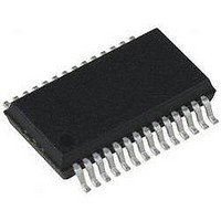
IC PIC MCU 16KB FLASH 28SSOP
Manufacturer
Microchip Technology
Series
PIC® XLP™ 18Fr
Specifications of PIC18LF24K22-I/SS
Core Size
8-Bit
Program Memory Size
16KB (8K x 16)
Core Processor
PIC
Speed
64MHz
Connectivity
I²C, SPI, UART/USART
Peripherals
Brown-out Detect/Reset, HLVD, POR, PWM, WDT
Number Of I /o
24
Program Memory Type
FLASH
Eeprom Size
256 x 8
Ram Size
768 x 8
Voltage - Supply (vcc/vdd)
1.8 V ~ 3.6 V
Data Converters
A/D 19x10b
Oscillator Type
Internal
Operating Temperature
-40°C ~ 85°C
Package / Case
28-SSOP (0.200", 5.30mm Width)
Controller Family/series
PIC18
No. Of I/o's
25
Eeprom Memory Size
256Byte
Ram Memory Size
768Byte
Cpu Speed
64MHz
No. Of Timers
7
Lead Free Status / RoHS Status
Lead free / RoHS Compliant


PIC18(L)F2X/4XK22
Packaging Information ..................................................... 463
PIE Registers ................................................................... 123
PIE1 Register ................................................................... 123
PIE2 Register ................................................................... 124
PIE3 Register3 ................................................................. 125
PIE4 Register ................................................................... 126
PIE5 Register ................................................................... 126
PIR Registers ................................................................... 118
PIR1 Register ................................................................... 118
PIR2 Register ................................................................... 119
PLL Frequency Multiplier ................................................... 39
POP .................................................................................. 396
POR. See Power-on Reset.
PORTA
PORTB
PORTC
PORTD
PORTE
Power Managed Modes ..................................................... 47
Power-on Reset (POR) ...................................................... 61
Power-up Delays ................................................................ 40
Power-up Timer (PWRT) .................................................... 40
Prescaler, Timer0 ............................................................. 159
PRI_IDLE Mode ................................................................. 52
PRI_RUN Mode ................................................................. 48
Program Counter ................................................................ 70
Program Memory
DS41412D-page 488
(ECCP) ..................................................................... 188
Marking .................................................................... 463
Associated Registers ............................................... 135
PORTA Register ...................................................... 133
TRISA Register ........................................................ 133
Associated Registers ............................................... 141
PORTB Register ...................................................... 138
Associated Registers ............................................... 145
PORTC Register ...................................................... 142
Associated Registers ............................................... 149
PORTD Register ...................................................... 146
TRISD Register ........................................................ 146
Associated Registers ............................................... 150
PORTE Register ...................................................... 149
and A/D Operation ................................................... 296
Effects on Clock Sources ........................................... 40
Entering ...................................................................... 47
Exiting Idle and Sleep Modes .................................... 54
Idle Modes ................................................................. 51
Multiple Sleep Functions ............................................ 48
Run Modes ................................................................. 48
Selecting .................................................................... 47
Sleep Mode ................................................................ 51
Summary (table) ........................................................ 47
Power-up Timer (PWRT) ........................................... 63
Time-out Sequence .................................................... 63
PCL, PCH and PCU Registers ................................... 70
PCLATH and PCLATU Registers .............................. 70
and Extended Instruction Set ..................................... 94
by Interrupt ......................................................... 54
by Reset ............................................................. 54
by WDT Time-out ............................................... 54
Without a Start-up Delay .................................... 54
PRI_IDLE ........................................................... 52
RC_IDLE ............................................................ 53
SEC_IDLE .......................................................... 52
PRI_RUN ........................................................... 48
SEC_RUN .......................................................... 48
Preliminary
Program Verification and Code Protection ...................... 362
PSTRxCON Register ....................................................... 206
PUSH ............................................................................... 396
PUSH and POP Instructions .............................................. 72
PUSHL ............................................................................. 412
PWM (ECCP Module)
PWM Mode. See Enhanced Capture/Compare/PWM ..... 188
PWM Steering .................................................................. 198
PWMxCON Register ........................................................ 206
R
RAM. See Data Memory.
RC_IDLE Mode .................................................................. 53
RC_RUN ............................................................................ 48
RCALL ............................................................................. 397
RCON Register .................................................................. 60
RCREG ............................................................................ 270
RCSTA Register .............................................................. 273
Reader Response ............................................................ 494
Register
Register File ....................................................................... 82
Registers
Code Protection ....................................................... 363
Instructions ................................................................ 75
Interrupt Vector .......................................................... 69
Look-up Tables .......................................................... 73
Map and Stack (diagram) .......................................... 70
Reset Vector .............................................................. 69
Associated Registers ............................................... 362
PWM Steering .......................................................... 198
Steering Synchronization ......................................... 198
Bit Status During Initialization .................................... 67
RCREG Register ..................................................... 279
ADCON0 (ADC Control 0) ....................................... 298
ADCON1 (ADC Control 1) ....................................... 299
ADCON2 (ADC Control 2) ....................................... 300
ADRESH (ADC Result High) with ADFM = 0) ......... 301
ADRESH (ADC Result High) with ADFM = 1) ......... 301
ADRESL (ADC Result Low) with ADFM = 0) ........... 301
ADRESL (ADC Result Low) with ADFM = 1) ........... 301
BAUDCON (Baud Rate Control) .............................. 274
BAUDCON (EUSART Baud Rate Control) .............. 274
CCPTMRS0 (PWM Timer Selection Control 0) ....... 204
CCPTMRS1 (PWM Timer Selection Control 1) ....... 204
CCPxCON (ECCPx Control) .................................... 201
CM1CON0 (C1 Control) ........................................... 310
CM2CON0 (C2 Control) ........................................... 311
CM2CON1 (C2 Control) ........................................... 314
CONFIG1H (Configuration 1 High) .......................... 351
CONFIG2H (Configuration 2 High) .......................... 353
CONFIG2L (Configuration 2 Low) ........................... 352
CONFIG3H (Configuration 3 High) .......................... 354
CONFIG4L (Configuration 4 Low) ........................... 355
CONFIG5H (Configuration 5 High) .......................... 356
CONFIG5L (Configuration 5 Low) ........................... 355
CONFIG6H (Configuration 6 High) .......................... 357
CONFIG6L (Configuration 6 Low) ........................... 356
CONFIG7H (Configuration 7 High) .......................... 358
CONFIG7L (Configuration 7 Low) ........................... 357
CTMUCONH (CTMU Control High) ......................... 329
CTMUCONL (CTMU Control Low) .......................... 330
CTMUICON (CTMU Current Control) ...................... 331
DEVID1 (Device ID 1) .............................................. 358
DEVID2 (Device ID 2) .............................................. 358
ECCPxAS (CCPx Auto-Shutdown Control) ............. 205
Two-Word .......................................................... 75
2010 Microchip Technology Inc.
Related parts for PIC18LF24K22-I/SS
Image
Part Number
Description
Manufacturer
Datasheet
Request
R

Part Number:
Description:
Manufacturer:
Microchip Technology Inc.
Datasheet:
Part Number:
Description:
Manufacturer:
Microchip Technology Inc.
Datasheet:
Part Number:
Description:
Manufacturer:
Microchip Technology Inc.
Datasheet:
Part Number:
Description:
Manufacturer:
Microchip Technology Inc.
Datasheet:
Part Number:
Description:
Manufacturer:
Microchip Technology Inc.
Datasheet:
Part Number:
Description:
Manufacturer:
Microchip Technology Inc.
Datasheet:
Part Number:
Description:
Manufacturer:
Microchip Technology Inc.
Datasheet:
Part Number:
Description:
Manufacturer:
Microchip Technology Inc.
Datasheet: