A16-1NGN Omron, A16-1NGN Datasheet - Page 48
A16-1NGN
Manufacturer Part Number
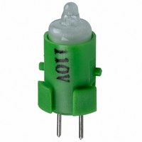
A16-1NGN
Description
NEON LAMP 110V GREEN FOR A16
Manufacturer
Omron
Type
Neon Lamp, 110 VoltsACr
Series
A16r
Datasheets
1.M2DA-7001.pdf
(265 pages)
2.A16-1NRN.pdf
(30 pages)
3.A16-2.pdf
(27 pages)
4.A165-CAA.pdf
(17 pages)
Specifications of A16-1NGN
Accessory Type
Neon Lamp Replacement
Supply Voltage
110V
Base Type
Bi-Pin
Colour
Green
Current Rating
1.5mA
Svhc
No SVHC (15-Dec-2010)
Illumination Colour
Green
Operating Lifetime
10000h
Voltage Rating Vac
110V
Average Bulb Lif
RoHS Compliant
Color
Green
Illumination
Illuminated
Height
13 mm
Illumination Color
Green
Mounting Style
Snap In
Termination Style
Tabs
Lamp Base Type
Bi-Pin
Rohs Compliant
Yes
Average Bulb Life
10000h
Lead Free Status / RoHS Status
Lead free / RoHS Compliant
For Use With/related Products
A16 Series
For Use With
Z1396 - SWTCH KNOB RND 3POS DPDT ILL GRNZ1393 - SWTCH KNOB RND 2POS SPDT ILL GRNZ1390 - SWTCH KNOB RND 2POS SPDT ILL GRNZ1384 - SWITCH KNB RECT 3POS DPDT ILLZ1381 - SWITCH KNB RECT 2POS SPDT ILLZ1378 - SWITCH KNB RECT 2POS SPDT ILLZ1372 - SWITCH KNOB SQ 3-POS DPDT ILLZ1369 - SWITCH KNOB SQ 2-POS SPDT ILLZ1366 - SWITCH KNOB SQ 2-POS SPDT ILLZ1308 - SWITCH PB RND MOM DPDT ILLUM GRNZ1304 - SWITCH PB RECT MOM DPDT ILLUMZ1300 - SWITCH PB SQ MOM DPDT ILLUM GRN
Lead Free Status / Rohs Status
Lead free / RoHS Compliant
Other names
A161NGN
Z1343
Z1343


A3C
Precautions
Refer to the Common Precautions for Pushbutton Switches on
page 14.
Correct Use
Mounting
To prevent electric shock or a fire, always make sure that the power
is turned OFF before mounting, removing, or wiring the Switch, or
performing maintenance.
Do not tighten the mounting ring excessively using pliers or a similar
tool. Excessive tightening may damage the mounting ring. (Tighten-
ing torque: 0.20 to 0.39 N⋅m)
Wiring
When wiring, use wires of a size appropriate for the applied voltage
and carry current. Perform soldering correctly under the conditions
given below. Using the Switch with the wires soldered incorrectly
may cause the terminals to become abnormally hot and cause a fire.
Wait for one minute after soldering before exerting any external
force on the solder.
Use a non-corrosive rosin liquid for the flux.
Perform wiring so that the wire sheaths do not come into contact
with the Switch. If this is unavoidable, use wires that can withstand
temperatures of 100°C min.
After wiring to the Switch has been completed, ensure an appropri-
ate insulation distance.
Operating Environment
Do not use in locations that are subject to dust, oil, or metal filings as
these may penetrate the interior of the Switch and cause malfunc-
tion.
46
Cat. No. A030-E1-05
Do not apply a voltage higher than the maximum rated operat-
ing voltage between the lamp terminals, as there is a risk that
the incandescent lamp or LED lamp will be damaged, and the
Pushbutton will be ejected.
When replacing the incandescent lamp, first turn OFF the
power supply, and then wait 10 minutes before performing re-
placement, as the lamp is still hot immediately after the power
is turned OFF, so there is a risk of burns.
1. Hand soldering: At 30 W within 5 seconds.
2. Dip soldering: At 240°C within 3 seconds.
!
Caution
ALL DIMENSIONS SHOWN ARE IN MILLIMETERS.
To convert millimeters into inches, multiply by 0.03937. To convert grams into ounces, multiply by 0.03527.
Using Microloads
Using a standard load switch for opening and closing a microload
circuit may cause wear on the contacts. Use the switch within the
operating range. (Refer to the diagram below.) Even when using mi-
croload models within the operating range shown below, if inrush
current occurs when the contact is opened or closed, it may cause
the contact surface to become rough, and so decrease life expec-
tancy. Therefore, insert a contact protection circuit where neces-
sary. The minimum applicable load is the N-level reference value.
This value indicates the malfunction reference level for the reliability
level of 60% (λ 60) (conforming to JIS C5003). The equation, λ 60 =
0.5 x 10
than 1/2,000,000 with a reliability level of 60%.
LED
Resistance to limit the LED current is provided internally and so an
external resistance is not required.
5 VDC
12 VDC
24 VDC
Rated voltage
–4
/times indicates that the estimated malfunction rate is less
30
24
12
5
0
0.15 mA
Invalid
area
33 Ω
270 Ω
1600 Ω
1 mA
Internal limiting resistance
Microload
area
26 mA
100 mA
Current (mA)
Standard
load area
150 mA
100 mA
A3C
Related parts for A16-1NGN
Image
Part Number
Description
Manufacturer
Datasheet
Request
R

Part Number:
Description:
SWITCH PB SQUARE MOM SPDT GREEN
Manufacturer:
Omron
Datasheet:

Part Number:
Description:
SWITCH PB SQUARE MOM SPDT WHITE
Manufacturer:
Omron
Datasheet:
Part Number:
Description:
SWITCH PB SQUARE MOM SPDT YELLOW
Manufacturer:
Omron
Datasheet:
Part Number:
Description:
SWITCH PB RECTANG MOM SPDT BLUE
Manufacturer:
Omron
Datasheet:
Part Number:
Description:
SWITCH PB RECTANG MOM SPDT YEL
Manufacturer:
Omron
Datasheet:
Part Number:
Description:
SWITCH PB SQUARE MOM SPDT BLUE
Manufacturer:
Omron
Datasheet:
Part Number:
Description:
SWITCH PB SQUARE MOM SPDT RED
Manufacturer:
Omron
Datasheet:
Part Number:
Description:
SWITCH PB RECTANG MOM SPDT GREEN
Manufacturer:
Omron
Datasheet:
Part Number:
Description:
SWITCH PB RECTANG MOM SPDT RED
Manufacturer:
Omron
Datasheet:

Part Number:
Description:
SWITCH PB RECTANG MOM SPDT WHITE
Manufacturer:
Omron
Datasheet:
Part Number:
Description:
SWITCH PB ROUND MOM SPDT BLUE
Manufacturer:
Omron
Datasheet:
Part Number:
Description:
SWITCH PB ROUND MOM SPDT GREEN
Manufacturer:
Omron
Datasheet:
Part Number:
Description:
SWITCH PB ROUND MOM SPDT RED
Manufacturer:
Omron
Datasheet:
Part Number:
Description:
SWITCH PB ROUND MOM SPDT WHITE
Manufacturer:
Omron
Datasheet:
Part Number:
Description:
SWITCH PB ROUND MOM SPDT YELLOW
Manufacturer:
Omron
Datasheet: