A16-1NGN Omron, A16-1NGN Datasheet - Page 16
A16-1NGN
Manufacturer Part Number
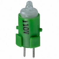
A16-1NGN
Description
NEON LAMP 110V GREEN FOR A16
Manufacturer
Omron
Type
Neon Lamp, 110 VoltsACr
Series
A16r
Datasheets
1.M2DA-7001.pdf
(265 pages)
2.A16-1NRN.pdf
(30 pages)
3.A16-2.pdf
(27 pages)
4.A165-CAA.pdf
(17 pages)
Specifications of A16-1NGN
Accessory Type
Neon Lamp Replacement
Supply Voltage
110V
Base Type
Bi-Pin
Colour
Green
Current Rating
1.5mA
Svhc
No SVHC (15-Dec-2010)
Illumination Colour
Green
Operating Lifetime
10000h
Voltage Rating Vac
110V
Average Bulb Lif
RoHS Compliant
Color
Green
Illumination
Illuminated
Height
13 mm
Illumination Color
Green
Mounting Style
Snap In
Termination Style
Tabs
Lamp Base Type
Bi-Pin
Rohs Compliant
Yes
Average Bulb Life
10000h
Lead Free Status / RoHS Status
Lead free / RoHS Compliant
For Use With/related Products
A16 Series
For Use With
Z1396 - SWTCH KNOB RND 3POS DPDT ILL GRNZ1393 - SWTCH KNOB RND 2POS SPDT ILL GRNZ1390 - SWTCH KNOB RND 2POS SPDT ILL GRNZ1384 - SWITCH KNB RECT 3POS DPDT ILLZ1381 - SWITCH KNB RECT 2POS SPDT ILLZ1378 - SWITCH KNB RECT 2POS SPDT ILLZ1372 - SWITCH KNOB SQ 3-POS DPDT ILLZ1369 - SWITCH KNOB SQ 2-POS SPDT ILLZ1366 - SWITCH KNOB SQ 2-POS SPDT ILLZ1308 - SWITCH PB RND MOM DPDT ILLUM GRNZ1304 - SWITCH PB RECT MOM DPDT ILLUMZ1300 - SWITCH PB SQ MOM DPDT ILLUM GRN
Lead Free Status / Rohs Status
Lead free / RoHS Compliant
Other names
A161NGN
Z1343
Z1343


Technical Information
For the individual precautions for a Switch, refer to the precautions
in the section for that Switch.
Cautions
Do not perform wiring or touch the charged parts of terminals while
power is being supplied to the Switch. Doing so may result in electric
shock.
Electrical Characteristics
Electrical Conditions
•
•
•
Inrush Current
•
•
•
14
Common Precautions
The switching load capacity of the Switch greatly varies between
AC and DC. Always be sure to apply the rated load. The control
capacity will drastically drop if it is a DC load. This is because a
DC load has no current zero-cross point, unlike an AC load.
Therefore, if an arc is generated, it may continue for a
comparatively long time. Furthermore, the current direction is
always the same, which results in a contact relocation
phenomena whereby the contacts easily stick to each other and
do not separate when the surfaces of the contacts are uneven.
Some types of load have a great difference between normal
current and inrush current. Make sure that the inrush current is
within the permissible value. The greater the inrush current in the
closed circuit is, the greater the contact abrasion or shift will be.
Consequently, contact weld, contact separation failures, or
insulation failures may result. Furthermore, the Switch may be
broken or damaged.
If the load is inductive, counter-electromotive voltage will be
generated. The higher the voltage is, the higher the generated
energy will be, which will increase the abrasion of the contacts
and contact relocation phenomena. Be sure to use the Switch
within the rated conditions.
Approximate control capacities are given in ratings tables, but
these alone are insufficient to guarantee correct operation. For
special types of load, with unusual switching voltage or current
waveforms, test whether correct operation is possible with the
actual load before application.
When switching for microloads (voltage or current), use a Switch
with microload specifications. The reliability of silver-plated
contacts, which are used in Switches for standard loads, will be
insufficient for microloads.
When switching microloads or very high loads that are beyond
the switching capacity of the Switch, connect a relay suitable for
the load.
i (Inrush current)
o (Steady-
state current)
Type of Load vs. Inrush Current
•
Note: Inductive loads can cause problems especially in DC cir-
Load Connections
Do not contact a single Switch to two power supplies that are differ-
ent in polarity or type.
Connection of Different Polarities
The power supply may short-circuit if the loads are connected in the
way shown in the “incorrect” example below.
Even in the “correct” example, note that the insulation performance
of the switch may deteriorate and the switch life may be shortened
because loads are connected to both contacts.
All the performance ratings given are for operation under the
following conditions unless otherwise specified.
Inductive load: A minimum power factor of 0.4 (AC) and a maxi-
Lamp load:
Motor load:
Incorrect
Correct
cuitry. Therefore, it is essential to know the time constants
(L/R) of the load.
mum time constant of 7 ms (DC)
An inrush current 10 times higher than the
steady-state current
An inrush current 6 times higher than the
steady-state current
Load
Solenoid
(Approximately 10 to 20 times higher)
Incandescent
lamp (Approximately 10 to 15 times
higher)
Technical Information
Motor
(Approximately
5 to 10 times
higher)
Relay
(Approxi-
mately 4 to 5
times higher)
Load
Load
Load
Related parts for A16-1NGN
Image
Part Number
Description
Manufacturer
Datasheet
Request
R

Part Number:
Description:
SWITCH PB SQUARE MOM SPDT GREEN
Manufacturer:
Omron
Datasheet:

Part Number:
Description:
SWITCH PB SQUARE MOM SPDT WHITE
Manufacturer:
Omron
Datasheet:
Part Number:
Description:
SWITCH PB SQUARE MOM SPDT YELLOW
Manufacturer:
Omron
Datasheet:
Part Number:
Description:
SWITCH PB RECTANG MOM SPDT BLUE
Manufacturer:
Omron
Datasheet:
Part Number:
Description:
SWITCH PB RECTANG MOM SPDT YEL
Manufacturer:
Omron
Datasheet:
Part Number:
Description:
SWITCH PB SQUARE MOM SPDT BLUE
Manufacturer:
Omron
Datasheet:
Part Number:
Description:
SWITCH PB SQUARE MOM SPDT RED
Manufacturer:
Omron
Datasheet:
Part Number:
Description:
SWITCH PB RECTANG MOM SPDT GREEN
Manufacturer:
Omron
Datasheet:
Part Number:
Description:
SWITCH PB RECTANG MOM SPDT RED
Manufacturer:
Omron
Datasheet:

Part Number:
Description:
SWITCH PB RECTANG MOM SPDT WHITE
Manufacturer:
Omron
Datasheet:
Part Number:
Description:
SWITCH PB ROUND MOM SPDT BLUE
Manufacturer:
Omron
Datasheet:
Part Number:
Description:
SWITCH PB ROUND MOM SPDT GREEN
Manufacturer:
Omron
Datasheet:
Part Number:
Description:
SWITCH PB ROUND MOM SPDT RED
Manufacturer:
Omron
Datasheet:
Part Number:
Description:
SWITCH PB ROUND MOM SPDT WHITE
Manufacturer:
Omron
Datasheet:
Part Number:
Description:
SWITCH PB ROUND MOM SPDT YELLOW
Manufacturer:
Omron
Datasheet: