A16-1NGN Omron, A16-1NGN Datasheet - Page 47
A16-1NGN
Manufacturer Part Number
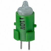
A16-1NGN
Description
NEON LAMP 110V GREEN FOR A16
Manufacturer
Omron
Type
Neon Lamp, 110 VoltsACr
Series
A16r
Datasheets
1.M2DA-7001.pdf
(265 pages)
2.A16-1NRN.pdf
(30 pages)
3.A16-2.pdf
(27 pages)
4.A165-CAA.pdf
(17 pages)
Specifications of A16-1NGN
Accessory Type
Neon Lamp Replacement
Supply Voltage
110V
Base Type
Bi-Pin
Colour
Green
Current Rating
1.5mA
Svhc
No SVHC (15-Dec-2010)
Illumination Colour
Green
Operating Lifetime
10000h
Voltage Rating Vac
110V
Average Bulb Lif
RoHS Compliant
Color
Green
Illumination
Illuminated
Height
13 mm
Illumination Color
Green
Mounting Style
Snap In
Termination Style
Tabs
Lamp Base Type
Bi-Pin
Rohs Compliant
Yes
Average Bulb Life
10000h
Lead Free Status / RoHS Status
Lead free / RoHS Compliant
For Use With/related Products
A16 Series
For Use With
Z1396 - SWTCH KNOB RND 3POS DPDT ILL GRNZ1393 - SWTCH KNOB RND 2POS SPDT ILL GRNZ1390 - SWTCH KNOB RND 2POS SPDT ILL GRNZ1384 - SWITCH KNB RECT 3POS DPDT ILLZ1381 - SWITCH KNB RECT 2POS SPDT ILLZ1378 - SWITCH KNB RECT 2POS SPDT ILLZ1372 - SWITCH KNOB SQ 3-POS DPDT ILLZ1369 - SWITCH KNOB SQ 2-POS SPDT ILLZ1366 - SWITCH KNOB SQ 2-POS SPDT ILLZ1308 - SWITCH PB RND MOM DPDT ILLUM GRNZ1304 - SWITCH PB RECT MOM DPDT ILLUMZ1300 - SWITCH PB SQ MOM DPDT ILLUM GRN
Lead Free Status / Rohs Status
Lead free / RoHS Compliant
Other names
A161NGN
Z1343
Z1343


A3C
Mounting the Insulation Cover
After securing the Switch to the panel using the mounting nut, pass
the lead wires through the holes in the Insulation Cover and then
perform wiring. Hold the Insulation Cover so that the cylindrical hole
is facing the Switch, and insert the lead wires from the end with the
barriers.
After wiring is completed, mount the Insulation Cover by pushing it
into the Switch.
Mounting the Dust Cover
Mounting the Switch Guard
1. The Dust Cover separates into 2 parts: the cap and the
2. Insert the Switch into the mounting frame. (Align the lock
3. Insert the Switch in the state described in step 2 into the
4. Mount the mounting nut from the back of the panel and tighten
5. Insert the cap into the mounting frame. Ensure that the entire
1. Insert the Switch into the Switch Guard.
2. Insert the Switch into the panel in the state described in step
3. Mount the mounting nut from the back of the panel and tighten
mounting frame.
projection with the recess on the mounting frame.)
panel. (Align the lock protrusion on the mounting frame with
the hole in the panel.)
it.
perimeter of the cap is properly inserted into the mounting
frame by pressing down on the cap from different directions.
1.
it.
Cap (transparent)
Insulation Cover attached to Switch
Switch Lock protrusions
Guard (transparent)
Holder (black)
Mounting frame
Switch terminal
Mounting nut
Panel
Panel
Mounting nut
A3C
45
Related parts for A16-1NGN
Image
Part Number
Description
Manufacturer
Datasheet
Request
R

Part Number:
Description:
SWITCH PB SQUARE MOM SPDT GREEN
Manufacturer:
Omron
Datasheet:

Part Number:
Description:
SWITCH PB SQUARE MOM SPDT WHITE
Manufacturer:
Omron
Datasheet:
Part Number:
Description:
SWITCH PB SQUARE MOM SPDT YELLOW
Manufacturer:
Omron
Datasheet:
Part Number:
Description:
SWITCH PB RECTANG MOM SPDT BLUE
Manufacturer:
Omron
Datasheet:
Part Number:
Description:
SWITCH PB RECTANG MOM SPDT YEL
Manufacturer:
Omron
Datasheet:
Part Number:
Description:
SWITCH PB SQUARE MOM SPDT BLUE
Manufacturer:
Omron
Datasheet:
Part Number:
Description:
SWITCH PB SQUARE MOM SPDT RED
Manufacturer:
Omron
Datasheet:
Part Number:
Description:
SWITCH PB RECTANG MOM SPDT GREEN
Manufacturer:
Omron
Datasheet:
Part Number:
Description:
SWITCH PB RECTANG MOM SPDT RED
Manufacturer:
Omron
Datasheet:

Part Number:
Description:
SWITCH PB RECTANG MOM SPDT WHITE
Manufacturer:
Omron
Datasheet:
Part Number:
Description:
SWITCH PB ROUND MOM SPDT BLUE
Manufacturer:
Omron
Datasheet:
Part Number:
Description:
SWITCH PB ROUND MOM SPDT GREEN
Manufacturer:
Omron
Datasheet:
Part Number:
Description:
SWITCH PB ROUND MOM SPDT RED
Manufacturer:
Omron
Datasheet:
Part Number:
Description:
SWITCH PB ROUND MOM SPDT WHITE
Manufacturer:
Omron
Datasheet:
Part Number:
Description:
SWITCH PB ROUND MOM SPDT YELLOW
Manufacturer:
Omron
Datasheet: