A16-1NGN Omron, A16-1NGN Datasheet - Page 221
A16-1NGN
Manufacturer Part Number
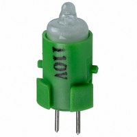
A16-1NGN
Description
NEON LAMP 110V GREEN FOR A16
Manufacturer
Omron
Type
Neon Lamp, 110 VoltsACr
Series
A16r
Datasheets
1.M2DA-7001.pdf
(265 pages)
2.A16-1NRN.pdf
(30 pages)
3.A16-2.pdf
(27 pages)
4.A165-CAA.pdf
(17 pages)
Specifications of A16-1NGN
Accessory Type
Neon Lamp Replacement
Supply Voltage
110V
Base Type
Bi-Pin
Colour
Green
Current Rating
1.5mA
Svhc
No SVHC (15-Dec-2010)
Illumination Colour
Green
Operating Lifetime
10000h
Voltage Rating Vac
110V
Average Bulb Lif
RoHS Compliant
Color
Green
Illumination
Illuminated
Height
13 mm
Illumination Color
Green
Mounting Style
Snap In
Termination Style
Tabs
Lamp Base Type
Bi-Pin
Rohs Compliant
Yes
Average Bulb Life
10000h
Lead Free Status / RoHS Status
Lead free / RoHS Compliant
For Use With/related Products
A16 Series
For Use With
Z1396 - SWTCH KNOB RND 3POS DPDT ILL GRNZ1393 - SWTCH KNOB RND 2POS SPDT ILL GRNZ1390 - SWTCH KNOB RND 2POS SPDT ILL GRNZ1384 - SWITCH KNB RECT 3POS DPDT ILLZ1381 - SWITCH KNB RECT 2POS SPDT ILLZ1378 - SWITCH KNB RECT 2POS SPDT ILLZ1372 - SWITCH KNOB SQ 3-POS DPDT ILLZ1369 - SWITCH KNOB SQ 2-POS SPDT ILLZ1366 - SWITCH KNOB SQ 2-POS SPDT ILLZ1308 - SWITCH PB RND MOM DPDT ILLUM GRNZ1304 - SWITCH PB RECT MOM DPDT ILLUMZ1300 - SWITCH PB SQ MOM DPDT ILLUM GRN
Lead Free Status / Rohs Status
Lead free / RoHS Compliant
Other names
A161NGN
Z1343
Z1343


A3A
Precautions
Operation
When operating an A3A, make sure that the A3A has a pushbutton.
Do not operate the A3A with a screwdriver or tweezers without
mounting a pushbutton to the A3A, otherwise the A3A may malfunc-
tion.
Mounting
When opening a hole on a panel to mount an A3A to the panel, make
sure that the hole has no burr.
When mounting a flange to the switching mechanism of an A3A,
make sure that the flange and the casing of the switching mecha-
nism are engaged securely.
Wiring
When soldering the terminals of an A3A, refer to the following.
Do not pull the terminals of any A3A with a force exceeding 5.34 N,
otherwise the joint part of the A3A may be damaged.
When soldering the terminals of an A3A, apply non-corrosive rosin
flux to the terminals.
After soldering the terminals of an A3A, do not wash the A3A with
any solvent.
When mounting an A3A to a PCB and soldering the terminals of the
A3A to the PCB, make sure that the flux will not rise above the sur-
face of the PCB.
Operating Environment
When using an A3A, make sure that dust, metal powder, or oil will
not penetrate into the interior of the A3A.
LED
The polarity of the LED is indicated on the back of the Switch. Wire
the LED correctly according to the polarity.
An A3A with a built-in LED does not have a limiting resistor. Connect
a limiting resistor.
The resistance can be calculated by using the following expression.
Note: Make sure that the limiting resistor connected to the built-in
Example
Conditions: Red LED with an I
From the red LED characteristic below, V
10 mA. Therefore, R = (24 V – 2 V)/0.01 A = 2,200 Ω.
Thus the recommended resistance is 2.2 kΩ at 0.5 W (2* x I
Note: A factor of 2 (marked with an asterisk) is applied because
Cat. No. A25-E1-06
1. For manual soldering: Use a soldering iron with the terminals
2. Do not impose any external force on the terminals for one
R = (E –V
E:
V
I
F
F
:
at a temperature of 350°C maximum within three seconds.
minute after the terminals are soldered.
: LED forward voltage (V)
LED of an A3A satisfies the characteristics of the built-in
LED. The mean forward current of the built-in LED must be
8 mA minimum.
the permissible wattage of the resistor must be twice as
large as the required wattage.
Applied voltage (V)
LED forward current (A)
F
)/I
F
(Ω)
ALL DIMENSIONS SHOWN ARE IN MILLIMETERS.
To convert millimeters into inches, multiply by 0.03937. To convert grams into ounces, multiply by 0.03527.
F
of –10 mA at 24 V and a Ta of 25°C.
F
will be 2 V when I
F
2
F
R).
is
LED Characteristics (V
Ta: Ambient Temperature
Pushbutton
When exchanging the Pushbutton (except the ones for the mechan-
ical indicator models) with a new one, pull out the Pushbutton from
the Switch, holding the Pushbutton in the longitudinal direction.
Do not remove the Pushbutton of the mechanical indicator model.
Engraving of Pushbutton
Depth of engraving:
0.3 mm max. for illuminating pushbutton
Since the Pushbutton is made of polycarbonate, use an alcohol-
based solvent when cleaning the Unit.
Pressing of Pushbutton
Apply firm pressure to the Pushbutton when operating it. In doing
so, however, do not apply a pressure greater than 11.8 N.
Red
Green
Yellow
Forward Voltage: Vr (V)
Forward Voltage: Vr (V)
Forward Voltage: Vr (V)
F
– I
F
Characteristics)
Ta = 25°C
Ta = 25°C
Ta = 25°C
A3A
219
Related parts for A16-1NGN
Image
Part Number
Description
Manufacturer
Datasheet
Request
R

Part Number:
Description:
SWITCH PB SQUARE MOM SPDT GREEN
Manufacturer:
Omron
Datasheet:

Part Number:
Description:
SWITCH PB SQUARE MOM SPDT WHITE
Manufacturer:
Omron
Datasheet:
Part Number:
Description:
SWITCH PB SQUARE MOM SPDT YELLOW
Manufacturer:
Omron
Datasheet:
Part Number:
Description:
SWITCH PB RECTANG MOM SPDT BLUE
Manufacturer:
Omron
Datasheet:
Part Number:
Description:
SWITCH PB RECTANG MOM SPDT YEL
Manufacturer:
Omron
Datasheet:
Part Number:
Description:
SWITCH PB SQUARE MOM SPDT BLUE
Manufacturer:
Omron
Datasheet:
Part Number:
Description:
SWITCH PB SQUARE MOM SPDT RED
Manufacturer:
Omron
Datasheet:
Part Number:
Description:
SWITCH PB RECTANG MOM SPDT GREEN
Manufacturer:
Omron
Datasheet:
Part Number:
Description:
SWITCH PB RECTANG MOM SPDT RED
Manufacturer:
Omron
Datasheet:

Part Number:
Description:
SWITCH PB RECTANG MOM SPDT WHITE
Manufacturer:
Omron
Datasheet:
Part Number:
Description:
SWITCH PB ROUND MOM SPDT BLUE
Manufacturer:
Omron
Datasheet:
Part Number:
Description:
SWITCH PB ROUND MOM SPDT GREEN
Manufacturer:
Omron
Datasheet:
Part Number:
Description:
SWITCH PB ROUND MOM SPDT RED
Manufacturer:
Omron
Datasheet:
Part Number:
Description:
SWITCH PB ROUND MOM SPDT WHITE
Manufacturer:
Omron
Datasheet:
Part Number:
Description:
SWITCH PB ROUND MOM SPDT YELLOW
Manufacturer:
Omron
Datasheet: