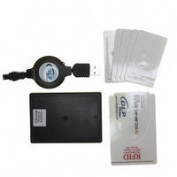
DLP-RFID1 DLP Design Inc, DLP-RFID1 Datasheet - Page 6

DLP-RFID1
Manufacturer Part Number
DLP-RFID1
Description
RFID READER/WRITER SNGL-CH
Manufacturer
DLP Design Inc
Datasheet
1.DLP-RFID1-OG.pdf
(7 pages)
Specifications of DLP-RFID1
Rf Type
Read / Write
Frequency
13.56MHz
Features
ISO15693, ISO18000-3, Tag-it™
Package / Case
Module
Lead Free Status / RoHS Status
Lead free / RoHS Compliant
Other names
813-1012
Available stocks
Company
Part Number
Manufacturer
Quantity
Price
Company:
Part Number:
DLP-RFID1
Manufacturer:
DLP Design Inc
Quantity:
135
9.2 INTEGRAL ANTENNA
The DLP-RFID1 is approved for use with the integral antenna only. Modifying the DLP-RFID1’s PCB
antenna or modifying the PCB to use an external antenna will void all agency compliance approvals.
A location for mounting an SMA connector (purchased separately) is available on the DLP-RFID1’s
printed circuit board. Mounting the SMA connector requires the removal of the RF shield from the PCB.
Additionally, the on-board antenna must be isolated from the signal path leading to the SMA connector
via the removal of capacitor C37. This output is designed to drive a 13.56MHz, 50-Ohm antenna. The
use of any other type of antenna may cause permanent damage to the DLP-RFID1.
9.3 FCC/IC REQUIREMENTS FOR MODULAR APPROVAL
Any changes or modifications to the DLP-RFID1’s printed circuit board could void the user’s authority to
operate the equipment.
9.4 WARNINGS
Operation is subject to the following two conditions: (1) This device may not cause harmful interference,
and (2) this device must accept any interference received, including interference that may cause
undesirable operation.
This device is intended for use under the following conditions:
1. The transmitter module may not be co-located with any other transmitter or antenna; and
2. The module is approved using the FCC’s “unlicensed modular transmitter approval” method.
As long as these two conditions are met, further transmitter testing will not be required. However, the
OEM integrator is still responsible for testing their end product for any additional compliance measures
necessitated by the installation of this module (i.e. digital device emissions, PC peripheral requirements,
etc.).
Note: In the event that these conditions cannot be met (i.e. co-location with another transmitter), then
the FCC authorization is no longer valid, and the corresponding FCC ID may not be used on the final
product. Under these circumstances, the OEM integrator will be responsible for re-evaluating the end
product (including the transmitter) and obtaining a separate FCC authorization.
9.5 OEM PRODUCT LABELING
The final end product must be labeled in a visible area with the following text:
“Contains TX FCC ID: SX90RFID1”
9.6 RF EXPOSURE
In order to comply with FCC RF exposure requirements, the antenna used for this transmitter must not
be co-located or operating in conjunction with any other antenna or transmitter.
DLP Design, Inc.
Rev 1.2 (May 2007)
6


