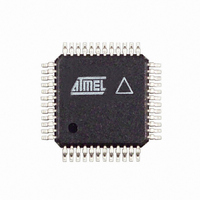
AT86RF211DAI-R Atmel, AT86RF211DAI-R Datasheet - Page 34

AT86RF211DAI-R
Manufacturer Part Number
AT86RF211DAI-R
Description
IC TXRX FR FSK 400-950MHZ 48-TQF
Manufacturer
Atmel
Datasheet
1.AT86RF211DAI-R.pdf
(48 pages)
Specifications of AT86RF211DAI-R
Frequency
400MHz ~ 950MHz
Data Rate - Maximum
100kbps
Modulation Or Protocol
FSK
Applications
ISM
Power - Output
7dBm ~ 12dBm
Sensitivity
-107dBm
Voltage - Supply
2.4 V ~ 3.6 V
Data Interface
PCB, Surface Mount
Antenna Connector
PCB, Surface Mount
Operating Temperature
-40°C ~ 85°C
Package / Case
48-TQFP Exposed Pad, 48-eTQFP, 48-HTQFP, 48-VQFP
Lead Free Status / RoHS Status
Contains lead / RoHS non-compliant
Memory Size
-
Current - Transmitting
-
Current - Receiving
-
DTR Register
34
AT86RF211
Table 11. Status Register Detailed Description
The DTR register allows the user to precisely adjust the offset of the data slicer input.
Table 12. DTR Overview
Register reset value = (20)
MSGMRATE
MSGDATL
MSGERR
WAKEUP
MRSSI
MVCC
Name
PLLL
-
Name
nbit
init
Number
of bits
10
1
6
6
1
1
1
5
Comments
PLL Lock flag
0: PLL unlocked
1: PLL locked
Measured RSSI level
Measured V
MOFFSET = 1
WAKEUP flag
Copy of the WAKEUP pin, but not affected by polarity selection.
0: no wake-up message received
1: wake-up message received
Reserved
Wake-up message error in test message mode
0: no error detected in the received message
1: message received with error
Wake-up message data length
length of the data stored in WUD (received message).
Wake-up message measured data rate
bit period extracted from message header of the wake-up
message.
Measured as a multiple of 1.56 µs (like RATE in WUR register).
0: 1 x 1.56 µs
(vv)
(3ff)
16
10
16
: vv x 1.56 µs
: 1024 x 1.56 µs
DSREF[3:0]
(1000)
5-2
CC
power supply voltage or discriminator output when
2
DISCHIGH
1
0
reset value: (000)
reset value: (00)
reset value: (00)
1942C–WIRE–06/02
reset value: 0
reset value: 0
reset value: 0
reset value: 0
reset value: 0
DISCLOW
0
0
16
16
16


