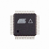
AT86RF211DAI-R Atmel, AT86RF211DAI-R Datasheet - Page 26

AT86RF211DAI-R
Manufacturer Part Number
AT86RF211DAI-R
Description
IC TXRX FR FSK 400-950MHZ 48-TQF
Manufacturer
Atmel
Datasheet
1.AT86RF211DAI-R.pdf
(48 pages)
Specifications of AT86RF211DAI-R
Frequency
400MHz ~ 950MHz
Data Rate - Maximum
100kbps
Modulation Or Protocol
FSK
Applications
ISM
Power - Output
7dBm ~ 12dBm
Sensitivity
-107dBm
Voltage - Supply
2.4 V ~ 3.6 V
Data Interface
PCB, Surface Mount
Antenna Connector
PCB, Surface Mount
Operating Temperature
-40°C ~ 85°C
Package / Case
48-TQFP Exposed Pad, 48-eTQFP, 48-HTQFP, 48-VQFP
Lead Free Status / RoHS Status
Contains lead / RoHS non-compliant
Memory Size
-
Current - Transmitting
-
Current - Receiving
-
Reset Register (RESET)
Control Register (CTRL1)
Table 5. CTRL1 Overview
Register reset value = (10000270
26
Name
Name
nbit
nbit
init
init
AT86RF211
TXLVL
PDN
(000 )
14-12
31
0
2
RXTX
30
TXFS
0
11
0
DATACLK
10
0
)
-
16
29
Writing in this register (0 or 1) triggers an asynchronous reset. This register can only be
written.
All registers return to reset state. The chip returns in power-down. So all the following
blocks are reset:
•
•
•
And with the power-down state, reset is applied to the following blocks:
•
•
•
•
•
•
•
0
All registers to default value
Wake-up function.
Clock recovery function.
Synthesizer dividers.
Clock recovery function.
PLL lock detect.
From powering up the supplies, it takes about 10 µs or at least 1.8V before the reset
state is established (Power-on Reset).
From reseting the device, one should wait about 10 µs before re-programming
RSSI detection block.
Discriminator clock (455 kHz).
RXFS
(10 )
9-8
2
TXLOCK
28
1
XTALFQ
7
0
Name
nbit
PAPDN
27
0
FSKBW
6
1
WUEN
26
0
FSKPOL
5
1
LNAGSEL
25
DSREF
0
4
1
MVCC
24
3
0
-
0
RESET
2
0
-
0
(000000)
TRSSI
23-18
MOFFSET
1942C–WIRE–06/02
2
1
0
HRSSI
(000)
17-15
2
0
0
-


