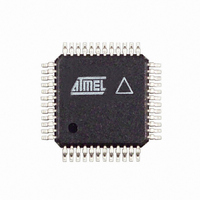
AT86RF211DAI-R Atmel, AT86RF211DAI-R Datasheet - Page 30

AT86RF211DAI-R
Manufacturer Part Number
AT86RF211DAI-R
Description
IC TXRX FR FSK 400-950MHZ 48-TQF
Manufacturer
Atmel
Datasheet
1.AT86RF211DAI-R.pdf
(48 pages)
Specifications of AT86RF211DAI-R
Frequency
400MHz ~ 950MHz
Data Rate - Maximum
100kbps
Modulation Or Protocol
FSK
Applications
ISM
Power - Output
7dBm ~ 12dBm
Sensitivity
-107dBm
Voltage - Supply
2.4 V ~ 3.6 V
Data Interface
PCB, Surface Mount
Antenna Connector
PCB, Surface Mount
Operating Temperature
-40°C ~ 85°C
Package / Case
48-TQFP Exposed Pad, 48-eTQFP, 48-HTQFP, 48-VQFP
Lead Free Status / RoHS Status
Contains lead / RoHS non-compliant
Memory Size
-
Current - Transmitting
-
Current - Receiving
-
Figure 34. Clock Recovery
30
DATAMSG
DATACLK
AT86RF211
If the tolerance is too high, the rate value is reached earlier, and the rate value could be
unstable (too big step).
If the tolerance is too low, it could be difficult to catch up the DATA and the function
could get lost.
Notice that maximum acceptable distance between two data transitions depends on the
precision of DATARATE versus transmitter actual data rate.
Synchronization mechanism is explained with the chronogram hereafter. The synchroni-
zation is done for the first bit. In worst case conditions, when data and clock arrive at the
same time, it begins at the second bit. Notice that the DATACLK signal is available as
soon as the DATACLK bit is programmed, whatever the state of DATAMSG pin.
The programmed data rate allows the creation of a basic clock at the programmed DAT-
ARATE frequency at the beginning of the reception. Then, the clock is shifted if
necessary from the tolerance value, depending on the previous DATA transition: the
clock is moved later or sooner, depending on the gap between CLOCK and DATA.
For example:
if DATARATE = 50 kbps, which is equivalent to a duration of 200 x T for 1 bit, with
T = 100 ns = base clock period.
if DATATOL = 2% x DATARATE = 4 x T.
•
This value must be programmed only when the DATA clock is needed on DATACLK
output pin of the chip.
The DATA rate can be programmed from 1 kbps to 64 kbps with 14 bits of CTRL2
register.
DATARATE is the period of the data rate and can be programmed with a resolution
given by the crystal oscillator period:
•
•
Some datarate values with the 10.245 MHz oscillator given for example:
200T
DATARATE[13:0]
(160)
(205)
(vv)
(534)
(1024)
DATARATE Programming
10.245 MHz oscillator, period = T = 97.6 ns
20.945 MHz oscillator, period = T = 95.5 ns
10
10
10
10
10
Expected value
Tol = 4T
Synchronized values with DATAMSG
Rate
64 kbps
50 kbps
……
19.2 kbps
10 kbps
Tol = 4T
Period
1 bit ~ 160 x T
1 bit ~ 205 x T
1 bit ~ vv x T
1 bit ~ 534 x T
1 bit ~ 1024 x T
Expected value
1942C–WIRE–06/02


