MNZB-24-B0 MeshNetics, MNZB-24-B0 Datasheet - Page 16
MNZB-24-B0
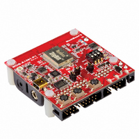
Manufacturer Part Number
MNZB-24-B0
Description
MOD 802.15.4/ZIGB 2.4GHZ RF PORT
Manufacturer
MeshNetics
Series
Zigbit™r
Datasheet
1.MNZB-24-B0.pdf
(24 pages)
Specifications of MNZB-24-B0
Frequency
2.4GHz
Data Rate - Maximum
250kbps
Modulation Or Protocol
802.15.4 Zigbee
Power - Output
3dBm
Sensitivity
-101dBm
Voltage - Supply
1.8 V ~ 3.6 V
Current - Receiving
19mA
Current - Transmitting
18mA
Data Interface
PCB, Surface Mount
Memory Size
128kBytes Flash, 8kBytes RAM, 4kBytes EEPROM
Antenna Connector
PCB, Surface Mount
Operating Temperature
-40°C ~ 85°C
Package / Case
Module
Lead Free Status / RoHS Status
Lead free / RoHS Compliant
Applications
-
Other names
758-1000-2
ZDM-A1281-B0
ZDM-A1281-B0


Normally, chip antennas are more tolerant of the board or enclosure materials in ZigBit’s neighborhood as well.
However, general recommendations given above for the PCB antenna design still apply.
The board design should prevent propagation of microwave field inside the board material. Electromagnetic waves
of high frequency may penetrate the board thus making the edges of the board radiate, which may distort the
antenna pattern. To eliminate this effect, metalized and grounded holes must be placed around the board’s edges
as shown..
Since the design of dual chip antenna is intended for installation on FR-4 board 1.6 mm thick, the antenna
performance may only be guaranteed for the particular board type and thickness.
© 2007 MeshNetics
3,5
PCB Layout with Dual Chip Antenna Module recommended for ZDM-A1281-A2
Bottom side
Top side
Module
Module
ZigBit
ZigBit
Zi gBi t™ O EM M odule s
60,0
Material: FR-4. thickness 1.6 mm
Metallization: 35 um
Coating: HASL, solder mask
All dimensions are in millimeters
Metallized through holes O0.3~0.4
through holes are unallowed
Recommended step 1 mm
2 through holes O3,0
Metallization, wires,
Area supporting
the components
Product Datasheet
Metallization
Page 16 of 24
Related parts for MNZB-24-B0
Image
Part Number
Description
Manufacturer
Datasheet
Request
R

Part Number:
Description:
MOD 802.15.4/ZIGB 2.4GHZ CHIPANT
Manufacturer:
MeshNetics
Datasheet:

Part Number:
Description:
BOARD DEV 802.15.4/ZIGB PCB ANT
Manufacturer:
MeshNetics
Datasheet:

Part Number:
Description:
BOARD DEV 802.15.4/ZIGB CHIP ANT
Manufacturer:
MeshNetics
Datasheet:

Part Number:
Description:
BOARD DEV 802.15.4/ZIGB SMA CONN
Manufacturer:
MeshNetics
Datasheet:

Part Number:
Description:
KIT DEV ZIGBIT 2.4GHZ COMPLETE
Manufacturer:
MeshNetics
Datasheet:
Part Number:
Description:
KIT DEV ZIGBIT 2.4GHZ LITE 45DAY
Manufacturer:
MeshNetics
Datasheet:


Part Number:
Description:
BOARD EVAL FOR MNZB-900-B0 W/ANT
Manufacturer:
MeshNetics
Datasheet:

Part Number:
Description:
BOARD EVAL MNZB-A24-UFL W/RP-SMA
Manufacturer:
MeshNetics

Part Number:
Description:
KIT DEV ZIGBIT 900 COMPLETE 1YR
Manufacturer:
MeshNetics
Datasheet:

Part Number:
Description:
KIT DEV ZIGBIT 900 LITE 45DAYS
Manufacturer:
MeshNetics
Datasheet:

