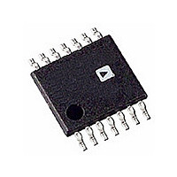
AD8343ARU-REEL Analog Devices Inc, AD8343ARU-REEL Datasheet - Page 21

AD8343ARU-REEL
Manufacturer Part Number
AD8343ARU-REEL
Description
IC MIXER ACTIVE HI-IP3 14-TSSOP
Manufacturer
Analog Devices Inc
Series
AD8343r
Datasheet
1.AD8343ARUZ.pdf
(32 pages)
Specifications of AD8343ARU-REEL
Rohs Status
RoHS non-compliant
Rf Type
Cellular, WLAN
Frequency
0Hz ~ 2.5GHz
Number Of Mixers
1
Gain
7dB
Noise Figure
14dB
Secondary Attributes
Up/Down Converter
Current - Supply
60mA
Voltage - Supply
4.5 V ~ 5.5 V
Package / Case
14-TSSOP (0.173", 4.40mm Width)
Operating Temperature (min)
-40C
Operating Temperature (max)
85C
Operating Temperature Classification
Industrial
Lead Free Status / Rohs Status
Not Compliant
Available stocks
Company
Part Number
Manufacturer
Quantity
Price
INPUT AND OUTPUT STABILITY CONSIDERATIONS
The differential configuration of the input and output ports of
the AD8343 raises the need to consider both differential and
common-mode RF stability of the device. Throughout the
following stability discussion, common mode is used to refer to
a signal that is referenced to ground. The equivalent common-
mode impedance is the value of impedance seen from the node
under discussion to ground. The book, Microwave Transistor
Amplifiers by Guillermo Gonzalez, also has an excellent section
covering stability of amplifiers.
The AD8343 is unconditionally stable for any differential
impedance, so device stability need not be considered with
respect to the differential terminations. However, the device is
potentially unstable (k factor is less than one) for some common-
mode impedances. Figure 61 and Figure 62 plot the input and
output common-mode stability regions, respectively. Figure 63
shows the test equipment configuration to measure these
stability circles.
The plotted stability circles in Figure 62 indicate that the guiding
principle for preventing stability problems due to common-
mode output loading is to avoid high-Q common-mode inductive
loading. This stability concern is of particular importance when
the output is taken from the device with a center-tapped trans-
former. The common-mode inductance to the center tap arises
from imperfect coupling between the halves of the primary
winding and produces an unstable common-mode loading
condition. Fortunately, a simple solution is to insert a ferrite
bead in series with the center tap, then provide effective RF
bypassing on the power supply side of the bead. The bead
develops substantial impedance (tens of ohms) by the time
a frequency of about 200 MHz is reached. The Murata
BLM21P300S is a possible choice for many applications.
FREQUENCY: 50MHz TO 2500MHz
150MHz
50MHz
Figure 61. Common-Mode Input Stability Circles
INCREMENT: 100MHz
Rev. B | Page 21 of 32
In cases where a transmission line balun is used at the output,
the solution deserves a bit more exploration. After the differ-
ential impedance matching network is designed, it is possible
to measure or simulate the common-mode impedance seen by
the device. This impedance is plotted against the stability circles
to ensure stable operation. An alternate topology for the matching
network is required if the proposed network produces an
unacceptable common-mode impedance.
FREQUENCY: 50MHz TO 2500MHz
VPOS
Figure 63. Impedance and Stability Circle Test Schematic
Figure 62. Common-Mode Output Stability Circles
1nH
4-PORT NETWORK ANALYZER
S PARAMETER TEST SET
BIAS
TEE
0.1µF
0.1µF
BIAS
TEE
1
2
3
4
5
6
7
BIAS
TEE
COMM
INPP
INPM
DCPL
VPOS
PWDN
COMM
AD8343
BIAS
TEE
COMM
COMM
COMM
OUTM
OUTP
LOIM
LOIP
INCREMENT: 100MHz
14
13
12
11
10
9
8
AD8343
50MHz
150MHz


