ATAKSTK511-8 Atmel, ATAKSTK511-8 Datasheet - Page 53
ATAKSTK511-8
Manufacturer Part Number
ATAKSTK511-8
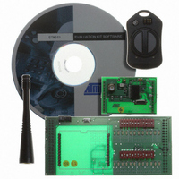
Description
KIT RF MODULE 868MHZ FOR STK500
Manufacturer
Atmel
Series
SmartRF®r
Type
Transmitter, Receiver, ASK, FSKr
Specifications of ATAKSTK511-8
Frequency
868MHz
Wireless Frequency
868 MHz
For Use With/related Products
ATSTK500
Lead Free Status / RoHS Status
Contains lead / RoHS non-compliant


AVR STK500 User Guide
Table 7-1. Troubleshooting Guide
Problem
The red power LED is not on.
The preprogrammed
example code does not
toggle the LEDs.
The AVR device cannot be
programmed.
Reason
The DC power cable is not
connected.
Wrong power supply is used.
The power switch is off.
There is no AVR device in the
socket.
The LEDs are not connected
to the I/O ports.
The Flash memory is erased.
The PC serial cable is not
connected.
The AVR device is inserted in
wrong socket.
The AVR device is inserted
with wrong orientation.
The target ISP header is not
connected.
The jumpers settings are
wrong.
The memory lock bits are
programmed.
Troubleshooting Guide
Solution
Connect the DC power cable
to the DC jack (page 2-3).
Check that the power supply
is of DC type 10 - 15V, min.
500 mA (page 2-3).
Turn on the power switch.
Plug the AVR device into the
right socket (page 2-3).
Connect the LEDS header to
the PORTD header, and the
SWITCHES header to the
PORTB header (page 3-3).
Connect STK500 to a PC
and reprogram the AVR
device (page 2-3).
Connect the serial cable to
the PC COM port and the
RS232 PROG port.
Check that the correct socket
is used (page 3-10).
Check that the notch on the
AVR socket matches the
notch on the AVR device.
Connect the 6-pin flexible
cable from ISP6PIN header
to the correct SPROG target
ISP header (page 3-10).
Set jumper to default setup
(page 3-15).
Erase the memory before
programming.
Section 7
Rev. 1925C–AVR–3/03
7-1
Related parts for ATAKSTK511-8
Image
Part Number
Description
Manufacturer
Datasheet
Request
R

Part Number:
Description:
DEV KIT FOR AVR/AVR32
Manufacturer:
Atmel
Datasheet:

Part Number:
Description:
INTERVAL AND WIPE/WASH WIPER CONTROL IC WITH DELAY
Manufacturer:
ATMEL Corporation
Datasheet:
Part Number:
Description:
Low-Voltage Voice-Switched IC for Hands-Free Operation
Manufacturer:
ATMEL Corporation
Datasheet:
Part Number:
Description:
MONOLITHIC INTEGRATED FEATUREPHONE CIRCUIT
Manufacturer:
ATMEL Corporation
Datasheet:
Part Number:
Description:
AM-FM Receiver IC U4255BM-M
Manufacturer:
ATMEL Corporation
Datasheet:
Part Number:
Description:
Monolithic Integrated Feature Phone Circuit
Manufacturer:
ATMEL Corporation
Datasheet:
Part Number:
Description:
Multistandard Video-IF and Quasi Parallel Sound Processing
Manufacturer:
ATMEL Corporation
Datasheet:
Part Number:
Description:
High-performance EE PLD
Manufacturer:
ATMEL Corporation
Datasheet:
Part Number:
Description:
8-bit Flash Microcontroller
Manufacturer:
ATMEL Corporation
Datasheet:
Part Number:
Description:
2-Wire Serial EEPROM
Manufacturer:
ATMEL Corporation
Datasheet: