ATAKSTK511-8 Atmel, ATAKSTK511-8 Datasheet - Page 11
ATAKSTK511-8
Manufacturer Part Number
ATAKSTK511-8
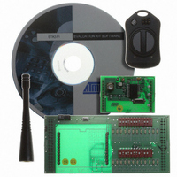
Description
KIT RF MODULE 868MHZ FOR STK500
Manufacturer
Atmel
Series
SmartRF®r
Type
Transmitter, Receiver, ASK, FSKr
Specifications of ATAKSTK511-8
Frequency
868MHz
Wireless Frequency
868 MHz
For Use With/related Products
ATSTK500
Lead Free Status / RoHS Status
Contains lead / RoHS non-compliant


3.1
AVR STK500 User Guide
Description of
User LEDs
Figure 3-1. STK500 Components
The STK500 starter kit includes 8 yellow LEDs and 8 push-button switches. The LEDs
and switches are connected to debug headers that are separated from the rest of the
board. They can be connected to the AVR devices with the supplied 10-wire cable to the
pin header of the AVR I/O ports. Figure 3-4 shows how the LEDs and switches can be
connected to the I/O port headers. The cables should be connected directly from the
port header to the LED or switch header. The cable should not be twisted. A red wire on
the cable indicates pin 1. Confirm that this is connected to pin 1 on each of the headers.
Figure 3-2 shows how the LED control is implemented. This solution will give the same
amount of light from the LED for all target voltages from 1.8V to 6.0V.
DataFlash Interface
Header
Header for LEDs
RS-232 Interface
Header
Switches
Header for
Switches
LEDs
Headers
for I/O Ports
Header for
Expansion Boards
Sockets for
Target AVR
Hardware Description
Target ISP Headers
Header for
Expansion Boards
Options Setting
Jumpers
6-pin ISP Header
Section 3
Target Reset
Push Button
10-pin ISP Header
(for External Target Only)
Rev. 1925C–AVR–3/03
Power Switch
Power Connector
Parallel Programming
Headers
RS-232 Port
for Programming
RS-232 Port
for Communication
Power LED
Master MCU
Status LED
Socket for
Crystal
Program Button
3-1
Related parts for ATAKSTK511-8
Image
Part Number
Description
Manufacturer
Datasheet
Request
R

Part Number:
Description:
DEV KIT FOR AVR/AVR32
Manufacturer:
Atmel
Datasheet:

Part Number:
Description:
INTERVAL AND WIPE/WASH WIPER CONTROL IC WITH DELAY
Manufacturer:
ATMEL Corporation
Datasheet:
Part Number:
Description:
Low-Voltage Voice-Switched IC for Hands-Free Operation
Manufacturer:
ATMEL Corporation
Datasheet:
Part Number:
Description:
MONOLITHIC INTEGRATED FEATUREPHONE CIRCUIT
Manufacturer:
ATMEL Corporation
Datasheet:
Part Number:
Description:
AM-FM Receiver IC U4255BM-M
Manufacturer:
ATMEL Corporation
Datasheet:
Part Number:
Description:
Monolithic Integrated Feature Phone Circuit
Manufacturer:
ATMEL Corporation
Datasheet:
Part Number:
Description:
Multistandard Video-IF and Quasi Parallel Sound Processing
Manufacturer:
ATMEL Corporation
Datasheet:
Part Number:
Description:
High-performance EE PLD
Manufacturer:
ATMEL Corporation
Datasheet:
Part Number:
Description:
8-bit Flash Microcontroller
Manufacturer:
ATMEL Corporation
Datasheet:
Part Number:
Description:
2-Wire Serial EEPROM
Manufacturer:
ATMEL Corporation
Datasheet: