ATAKSTK511-8 Atmel, ATAKSTK511-8 Datasheet - Page 37
ATAKSTK511-8
Manufacturer Part Number
ATAKSTK511-8
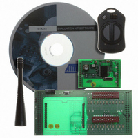
Description
KIT RF MODULE 868MHZ FOR STK500
Manufacturer
Atmel
Series
SmartRF®r
Type
Transmitter, Receiver, ASK, FSKr
Specifications of ATAKSTK511-8
Frequency
868MHz
Wireless Frequency
868 MHz
For Use With/related Products
ATSTK500
Lead Free Status / RoHS Status
Contains lead / RoHS non-compliant


3.11.2
3.11.3
3.11.4
3.11.5
AVR STK500 User Guide
PROGRAM Push
Button
Main Power LED
Target Power LED
Status LED
Future versions of AVR Studio may upgrade the master microcontroller on STK500.
AVR Studio will then detect old software versions of STK500 and update the Flash pro-
gram memory of the master microcontroller. To do this, the user is required to push the
PROGRAM button when powering on STK500. AVR Studio issues instructions on how
to perform the upgrade during the upgrade process.
The red power LED is directly connected to the STK500 main power supply. The power
LED is always lit when power is applied to STK500.
The target power LED is connected to VCC lines (VTG) on the target AVR devices in the
sockets. The target power LED is lit when power is applied to the target AVR device.
The PROGRAM LED is a 3-color LED. During programming, the LED is yellow. When
the target AVR device is successfully programmed, the LED will turn green. If program-
ming fails, the LED will turn red to indicate that programming failed. When programming
fails, check the troubleshooting guide in Section 7 on page 7-1. During start-up, the sta-
tus LED will shift from red, through yellow, to green to indicate that the master
microcontroller is ready.
Hardware Description
1925C–AVR–3/03
3-27
Related parts for ATAKSTK511-8
Image
Part Number
Description
Manufacturer
Datasheet
Request
R

Part Number:
Description:
DEV KIT FOR AVR/AVR32
Manufacturer:
Atmel
Datasheet:

Part Number:
Description:
INTERVAL AND WIPE/WASH WIPER CONTROL IC WITH DELAY
Manufacturer:
ATMEL Corporation
Datasheet:
Part Number:
Description:
Low-Voltage Voice-Switched IC for Hands-Free Operation
Manufacturer:
ATMEL Corporation
Datasheet:
Part Number:
Description:
MONOLITHIC INTEGRATED FEATUREPHONE CIRCUIT
Manufacturer:
ATMEL Corporation
Datasheet:
Part Number:
Description:
AM-FM Receiver IC U4255BM-M
Manufacturer:
ATMEL Corporation
Datasheet:
Part Number:
Description:
Monolithic Integrated Feature Phone Circuit
Manufacturer:
ATMEL Corporation
Datasheet:
Part Number:
Description:
Multistandard Video-IF and Quasi Parallel Sound Processing
Manufacturer:
ATMEL Corporation
Datasheet:
Part Number:
Description:
High-performance EE PLD
Manufacturer:
ATMEL Corporation
Datasheet:
Part Number:
Description:
8-bit Flash Microcontroller
Manufacturer:
ATMEL Corporation
Datasheet:
Part Number:
Description:
2-Wire Serial EEPROM
Manufacturer:
ATMEL Corporation
Datasheet: