1321XEVK Freescale Semiconductor, 1321XEVK Datasheet - Page 45
1321XEVK
Manufacturer Part Number
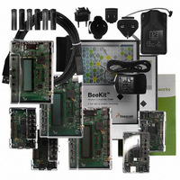
1321XEVK
Description
KIT EVALUATION FOR 1321X
Manufacturer
Freescale Semiconductor
Type
Zigbeer
Specifications of 1321XEVK
Frequency
2.4GHz
Wireless Frequency
2.4 GHz
Modulation
DSSS OQPSK
Security
128 bit AES
Operating Voltage
2 VDC to 3.4 VDC
Operating Temperature Range
- 40 C to + 85 C
For Use With/related Products
MC1321x
Lead Free Status / RoHS Status
Contains lead / RoHS non-compliant


5.7.8
Development support systems in the include the background debug controller (BDC) and the on-chip
debug module (DBG). The BDC provides a single-wire debug interface to the target MCU that provides a
convenient interface for programming the on-chip FLASH and other non-volatile memories. The BDC is
also the primary debug interface for development and allows non-intrusive access to memory data and
traditional debug features such as CPU register modify, breakpoints, and single instruction trace
commands.
Address and data bus signals are not available on external pins (not even in test modes). Debug is done
through commands fed into the MCU via the single-wire background debug interface. The debug module
provides a means to selectively trigger and capture bus information so an external development system can
reconstruct what happened inside the MCU on a cycle-by-cycle basis without having external access to the
address and data signals.
The alternate BDC clock source for HCS08 is the ICGLCLK.
5.7.8.1
Features of the background debug controller (BDC) include:
Features of the debug module (DBG) include:
Freescale Semiconductor
•
•
•
•
•
•
•
•
•
•
•
•
•
•
Single pin for mode selection and background communications
BDC registers are not located in the memory map
SYNC command to determine target communications rate
Non-intrusive commands for memory access
Active background mode commands for CPU register access
GO and TRACE1 commands
BACKGROUND command can wake CPU from stop or wait modes
One hardware address breakpoint built into BDC
Oscillator runs in stop mode, if BDC enabled
COP watchdog disabled while in active background mode
Two trigger comparators:
— Two address + read/write (R/W) or
— One full address + data + R/W
Flexible 8-word by 16-bit FIFO (first-in, first-out) buffer for capture information:
— Change-of-flow addresses or
— Event-only data
Two types of breakpoints:
— Tag breakpoints for instruction opcodes
— Force breakpoints for any address access
Nine trigger modes:
Development Support
Development Support Features
MC13211/212/213 Technical Data, Rev. 1.8
45
Related parts for 1321XEVK
Image
Part Number
Description
Manufacturer
Datasheet
Request
R

Part Number:
Description:
Manufacturer:
Freescale Semiconductor, Inc
Datasheet:
Part Number:
Description:
Manufacturer:
Freescale Semiconductor, Inc
Datasheet:
Part Number:
Description:
Manufacturer:
Freescale Semiconductor, Inc
Datasheet:
Part Number:
Description:
Manufacturer:
Freescale Semiconductor, Inc
Datasheet:
Part Number:
Description:
Manufacturer:
Freescale Semiconductor, Inc
Datasheet:
Part Number:
Description:
Manufacturer:
Freescale Semiconductor, Inc
Datasheet:
Part Number:
Description:
Manufacturer:
Freescale Semiconductor, Inc
Datasheet:
Part Number:
Description:
Manufacturer:
Freescale Semiconductor, Inc
Datasheet:
Part Number:
Description:
Manufacturer:
Freescale Semiconductor, Inc
Datasheet:
Part Number:
Description:
Manufacturer:
Freescale Semiconductor, Inc
Datasheet:
Part Number:
Description:
Manufacturer:
Freescale Semiconductor, Inc
Datasheet:
Part Number:
Description:
Manufacturer:
Freescale Semiconductor, Inc
Datasheet:
Part Number:
Description:
Manufacturer:
Freescale Semiconductor, Inc
Datasheet:
Part Number:
Description:
Manufacturer:
Freescale Semiconductor, Inc
Datasheet:
Part Number:
Description:
Manufacturer:
Freescale Semiconductor, Inc
Datasheet: