1321XEVK Freescale Semiconductor, 1321XEVK Datasheet - Page 13
1321XEVK
Manufacturer Part Number
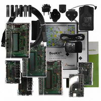
1321XEVK
Description
KIT EVALUATION FOR 1321X
Manufacturer
Freescale Semiconductor
Type
Zigbeer
Specifications of 1321XEVK
Frequency
2.4GHz
Wireless Frequency
2.4 GHz
Modulation
DSSS OQPSK
Security
128 bit AES
Operating Voltage
2 VDC to 3.4 VDC
Operating Temperature Range
- 40 C to + 85 C
For Use With/related Products
MC1321x
Lead Free Status / RoHS Status
Contains lead / RoHS non-compliant


2.2
The MCU provides control for the 802.15.4 modem. The required interconnects between the devices are
routed onboard the SiP. In addition, the signals are brought out to external pads primarily for use as test
points. These signals can be useful when writing and debugging software.
Freescale Semiconductor
1
2
Pin #
During low power modes, input must remain driven by MCU.
By default MISO is tri-stated when CE is negated. For low power operation, miso_hiz_en (Bit 11, Register 07) should be set
to zero so that MISO is driven low when CE is negated.
43
44
46
PTE5/SPSCK1
PTE4/MOSI1
PTE3/MISO1
Internal Functional Interconnects
MCU Signal
PTE2/SS1
PTE6
PTE7
PTD0
PTD1
PTD3
IRQ
To use the MCU and modem signals as described in
to be programmed appropriately for the stated function.
Modem Signal
RXTXEN
SPICLK
M_RST
GPIO2
GPIO1
M_IRQ
MOSI
MISO
ATTN
CE
1
Table 3. Internal Functional Interconnects
1
2
1
1
MC13211/212/213 Technical Data, Rev. 1.8
Modem GPIO2 output acts as “CRC Valid” status indicator for Stream Data
Mode to MCU.
Modem GPIO1 output acts as “Out of Idle” status indicator for Stream Data
Mode to MCU.
MCU Port D Bit 0 drives the attention (ATTN) input of the modem to wake
modem from Hibernate or Doze Mode.
MCU SPI master SPI clock output drives modem SPICLK slave clock input.
MCU SPI master MOSI output drives modem slave MOSI input
Modem SPI slave MISO output drives MCU master MISO input
MCU SPI master SS output drives modem slave CE input
Modem interrupt request M_IRQ output drives MCU IRQ input
MCU Port D Bit 1 drives the RXTXEN input to the modem to enable TX or RX
or CCA operations.
MCU Port D Bit 3 drives the reset M_RST input to the modem.
NOTE
Table
Description
3, the MCU needs
13
Related parts for 1321XEVK
Image
Part Number
Description
Manufacturer
Datasheet
Request
R

Part Number:
Description:
Manufacturer:
Freescale Semiconductor, Inc
Datasheet:
Part Number:
Description:
Manufacturer:
Freescale Semiconductor, Inc
Datasheet:
Part Number:
Description:
Manufacturer:
Freescale Semiconductor, Inc
Datasheet:
Part Number:
Description:
Manufacturer:
Freescale Semiconductor, Inc
Datasheet:
Part Number:
Description:
Manufacturer:
Freescale Semiconductor, Inc
Datasheet:
Part Number:
Description:
Manufacturer:
Freescale Semiconductor, Inc
Datasheet:
Part Number:
Description:
Manufacturer:
Freescale Semiconductor, Inc
Datasheet:
Part Number:
Description:
Manufacturer:
Freescale Semiconductor, Inc
Datasheet:
Part Number:
Description:
Manufacturer:
Freescale Semiconductor, Inc
Datasheet:
Part Number:
Description:
Manufacturer:
Freescale Semiconductor, Inc
Datasheet:
Part Number:
Description:
Manufacturer:
Freescale Semiconductor, Inc
Datasheet:
Part Number:
Description:
Manufacturer:
Freescale Semiconductor, Inc
Datasheet:
Part Number:
Description:
Manufacturer:
Freescale Semiconductor, Inc
Datasheet:
Part Number:
Description:
Manufacturer:
Freescale Semiconductor, Inc
Datasheet:
Part Number:
Description:
Manufacturer:
Freescale Semiconductor, Inc
Datasheet: