STM32L152-EVAL STMicroelectronics, STM32L152-EVAL Datasheet - Page 8
STM32L152-EVAL
Manufacturer Part Number
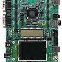
STM32L152-EVAL
Description
BOARD EVALUATION FOR STM32L
Manufacturer
STMicroelectronics
Type
MCUr
Specifications of STM32L152-EVAL
New! Us2012 Catalog Page
STM8L-Discovery_STM32L152-EVAL
Contents
Board
Processor To Be Evaluated
STM32L1xxx
Interface Type
UART
Operating Supply Voltage
2 V to 3.6 V
For Use With/related Products
STM32L
Lead Free Status / RoHS Status
Lead free / RoHS Compliant
Other names
497-10842


Hardware and layout
8/44
Table 1.
JP12
(selects one of
the four possible
power supply
resources)
JP13
JP4
Jumper
Power related jumpers
For power supply from jack (CN12) to the STM32L152-EVAL
only, JP12 is set as shown.
For power supply from daughterboard connector (CN6) to
STM32L152-EVAL only, JP12 is set as shown.
For power supply from USB (CN1) to STM32L152-EVAL only,
JP12 is set as shown.
For power supply from USB connector of ST-LINK/V2 (CN11)
to STM32L152-EVAL only, JP12 is set as shown (default
setting).
For power supply from power supply jack (CN12) to both
STM32L152-EVAL and daughterboard connected on CN6 and
CN7, JP12 is set as shown (daughterboard must not have its
own power supply connected).
VDD is connected to fixed +3.3V DC power when JP13 is set
as shown (default setting).
VDD is connected to adjustable DC power from 1.65 V to 3.6 V
when JP13 is set as shown.
VDD power is directly connected to MCU VDD when JP4 is set
as shown (default setting).
Note: For manual IDD measurement the jumper on JP4 must
be removed and replaced by an ammeter connected between
pin 1 and 2 of JP4.
Connect VDD power to MCU with current-sampling resistor,
1 Ohm or 1 KOhm, in series for IDD current measurement
when JP4 is set as shown.
Doc ID 18141 Rev 1
Description
Jumper setting
UM1018
1
1
1
1
2
2
2
2
3
3
3
3
Related parts for STM32L152-EVAL
Image
Part Number
Description
Manufacturer
Datasheet
Request
R

Part Number:
Description:
IAR� starter kit for STM32L EnergyLite 32-bit microcontrollers
Manufacturer:
STMICROELECTRONICS [STMicroelectronics]
Datasheet:

Part Number:
Description:
MCU, MPU & DSP Development Tools STM32L152VBT6 IAR 32KB Workbench
Manufacturer:
STMicroelectronics
Datasheet:

Part Number:
Description:
16/32-BITS MICROS
Manufacturer:
STMicroelectronics
Datasheet:
Part Number:
Description:
BOARD, EVAL, STM32L-DISCOVERY
Manufacturer:
STMicroelectronics
Datasheet:
Part Number:
Description:
STMicroelectronics [RIPPLE-CARRY BINARY COUNTER/DIVIDERS]
Manufacturer:
STMicroelectronics
Datasheet:
Part Number:
Description:
STMicroelectronics [LIQUID-CRYSTAL DISPLAY DRIVERS]
Manufacturer:
STMicroelectronics
Datasheet:

Part Number:
Description:
BOARD EVAL FOR MEMS SENSORS
Manufacturer:
STMicroelectronics
Datasheet:
Part Number:
Description:
NPN TRANSISTOR POWER MODULE
Manufacturer:
STMicroelectronics
Datasheet:
Part Number:
Description:
TURBOSWITCH ULTRA-FAST HIGH VOLTAGE DIODE
Manufacturer:
STMicroelectronics
Datasheet:
Part Number:
Description:
Manufacturer:
STMicroelectronics
Datasheet:
Part Number:
Description:
DIODE / SCR MODULE
Manufacturer:
STMicroelectronics
Datasheet:
Part Number:
Description:
DIODE / SCR MODULE
Manufacturer:
STMicroelectronics
Datasheet: