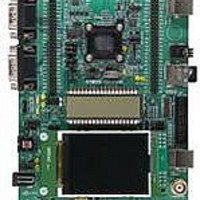
STM32L152-EVAL STMicroelectronics, STM32L152-EVAL Datasheet - Page 13

STM32L152-EVAL
Manufacturer Part Number
STM32L152-EVAL
Description
BOARD EVALUATION FOR STM32L
Manufacturer
STMicroelectronics
Type
MCUr
Specifications of STM32L152-EVAL
New! Us2012 Catalog Page
STM8L-Discovery_STM32L152-EVAL
Contents
Board
Processor To Be Evaluated
STM32L1xxx
Interface Type
UART
Operating Supply Voltage
2 V to 3.6 V
For Use With/related Products
STM32L
Lead Free Status / RoHS Status
Lead free / RoHS Compliant
Other names
497-10842
UM1018
2.13
Comparator
3 I/Os are used to implement a comparator feature as shown in
●
●
●
Figure 3.
Jumper JP17 allows 3 different usages of the potentiometer as shown in
Table 10.
JP17
Jumper
Comparator non-inverting input PB4 connected to LDR (R34).
Comparator inverting input PB3 connected to potentiometer (RV3) used as variable
threshold input for comparison to luminosity measured on LDR.
Comparator non-inverting input PB5 connected to potentiometer (RV3) used as
analogue voltage input for comparison with internal voltage reference (for instance
Band gap) in order to test analogue Wakeup feature of the MCU.
Potentiometer RV3 is connected to ADC input PB12. Used as ADC input
when JP17 is set as shown (default setting).
Potentiometer RV3 used as LDR variable threshold. Input is connected to
comparator inverting input GPCOMP_IN- (PB3) when JP17 is set as shown.
Potentiometer RV3 is connected to non-inverting input GPCOMP_IN+(PB5).
The comparator inverting input can be connected to ¼ band gap, ½ band
gap, band gap or DAC internally in order to test the possibility to wakeup the
MCU when an external voltage reaches a programmable threshold when
JP17 is set as shown.
STM32L152-EVAL comparator features
Comparator and potentiometer related jumpers
Doc ID 18141 Rev 1
Description
Figure
Hardware and layout
3.
Table
10.
Setting
13/44


