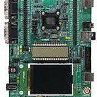
STM32L152-EVAL STMicroelectronics, STM32L152-EVAL Datasheet - Page 7

STM32L152-EVAL
Manufacturer Part Number
STM32L152-EVAL
Description
BOARD EVALUATION FOR STM32L
Manufacturer
STMicroelectronics
Type
MCUr
Specifications of STM32L152-EVAL
New! Us2012 Catalog Page
STM8L-Discovery_STM32L152-EVAL
Contents
Board
Processor To Be Evaluated
STM32L1xxx
Interface Type
UART
Operating Supply Voltage
2 V to 3.6 V
For Use With/related Products
STM32L
Lead Free Status / RoHS Status
Lead free / RoHS Compliant
Other names
497-10842
UM1018
2.1
Note:
2.2
Note:
Development and debug support
Version 2 of the ST-LINK, called ST-LINK/V2, is embedded on the board. This tool allows on-
board program loading and debugging of the STM32L using the JTAG or SWD interface.
Third-party debug tools are also supported by the JTAG (CN9) or Trace (CN8) connectors.
To communicate with the embedded ST-LINK/V2, a specific driver needs to be installed on
your PC. To download and install this driver, refer to the Software and development tools
page for the ultra low power STM32L family available on www.st.com (the install shield is
called ST-LINK_V2_USBdriver.exe).
The embedded ST-LINK/V2 connects to the PC via a standard USB cable from connector
CN11. The bicolor LED LD5 (COM) advises on the status of the communication as follows:
1.
2.
3.
4.
5.
6.
7.
It is possible to power the board via CN11 (embedded ST/LINK/V2 USB connector) even if
an external tool is connected to CN8 (trace) or CN9 (external JTAG and SWD).
Power supply
The STM32L152-EVAL is designed to be powered by a 5 V DC power supply and to be
protected by PolyZen from a wrong power plug-in event. It is possible to configure the
evaluation board to use any of the following four power supply sources by setting jumpers
JP12, JP13 and JP4 (see
●
The AC220V to DC5V power adapter PSU-5V2A (recommended, can be ordered from ST
order code PSU-5V2A) or equivalent (polarity compatible with CN12) can be used to power
the STM32L152-EVAL board via its power jack CN12.
●
●
●
Various LEDs indicate the power status:
●
●
●
●
Slow blinking Red, then Off: At power-on before USB initialization.
Fast blinking Red, then Off: After the first correct communication between PC and ST-
Link/V2 (enumeration).
Red On: When initialization between PC and ST-LINK/V2 is successfully finished.
Green On: After successful target communication initialization.
Blinking Red/Green: During communication with target.
Green On: Communication finished and OK.
Orange On: Communication failure.
5 V DC power adapter connected to CN12, the power jack on the board (power supply
unit (PSU on silk screen)). The external power supply is not provided with the board but
can be ordered separately.
5 V DC power with 500 mA limitation from CN11, the USB type B connector of ST-
LINK/V2 (USB 5 V power source (ST-LINK/V2 on silkscreen)).
5 V DC power with 500 mA limitation from CN1, the USB type B connector (5 V power
source (USB on silkscreen)).
5 V DC power from CN6, the extension connector for daughterboard (daughterboard
power source (Daughter board on JP12 silkscreen).
Red LED LD9 is lit when the STM32L152-EVAL board is powered correctly by 5 V.
Red LED LD8 is lit when MCU is powered by low voltage (VDD < 1.8 V).
Yellow LED LD7 is lit when MCU is powered by voltage (1.8 V<VDD<2.2 V).
Green LED LD6 is lit when MCU is powered by voltage (2.2 V<VDD).
Table
Doc ID 18141 Rev 1
1).
Hardware and layout
7/44


