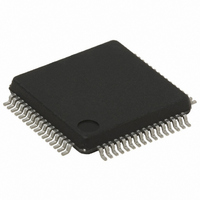
ST72F561R9TA STMicroelectronics, ST72F561R9TA Datasheet - Page 263

ST72F561R9TA
Manufacturer Part Number
ST72F561R9TA
Description
IC MCU 8BIT 60K FLASH 64-LQFP
Manufacturer
STMicroelectronics
Series
ST7r
Datasheet
1.ST72F561K6T6.pdf
(265 pages)
Specifications of ST72F561R9TA
Core Processor
ST7
Core Size
8-Bit
Speed
8MHz
Connectivity
CAN, LINSCI, SPI
Peripherals
LVD, POR, PWM, WDT
Number Of I /o
48
Program Memory Size
60KB (60K x 8)
Program Memory Type
FLASH
Ram Size
2K x 8
Voltage - Supply (vcc/vdd)
3.8 V ~ 5.5 V
Data Converters
A/D 16x10b
Oscillator Type
External
Operating Temperature
-40°C ~ 85°C
Package / Case
64-LQFP
For Use With
497-8374 - BOARD DEVELOPMENT FOR ST72F561
Lead Free Status / RoHS Status
Lead free / RoHS Compliant
Eeprom Size
-
Available stocks
Company
Part Number
Manufacturer
Quantity
Price
Company:
Part Number:
ST72F561R9TA
Manufacturer:
STMicroelectronics
Quantity:
10 000
Company:
Part Number:
ST72F561R9TATR
Manufacturer:
STMicroelectronics
Quantity:
10 000
- Current page: 263 of 265
- Download datasheet (10Mb)
IMPORTANT NOTES (Cont’d)
Occurrence
The occurrence of the problem is random and pro-
portional to the baud rate. With a transmit frequen-
cy
SCIBRR = 0xC9), the wrong break duration occur-
rence is around 1%.
Analysis
The LIN protocol specifies a minimum of 13 bits for
the break duration, but there is no maximum value.
Nevertheless, the maximum length of the header
is specified as (14+10+10+1) x 1.4 = 49 bits. This
is composed of:
- the synch break field (14 bits)
- the synch field (10 bits)
- the identifier field (10 bits)
Every LIN frame starts with a break character.
Adding an idle character increases the length of
each header by 10 bits. When the problem occurs,
the header length is increased by 11 bits and be-
comes ((14+11)+10+10+1) = 45 bits.
To conclude, the problem is not always critical for
LIN communication if the software keeps the time
between the sync field and the ID smaller than 4
bits, that is, 208µs at 19200 baud.
of
19200
baud
(f
CPU
= 8
MHz
and
The workaround is the same as for SCI mode but
considering the low probability of occurrence (1%),
it may be better to keep the break generation se-
quence as it is.
16.2.2 16-bit and 8-bit Timer PWM Mode
In PWM mode, the first PWM pulse is missed after
writing the value FFFCh in the OC1R or OC2R
register.
16.3 ROM DEVICES ONLY
16.3.1 16-bit Timer PWM Mode Buffering
Feature Change
In all devices, the frequency and period of the
PWM signal are controlled by comparing the coun-
ter with a 16-bit buffer updated by the OCiHR and
OCiLR registers. In ROM devices, contrary to the
description in
output compare function is not inhibited after a
write instruction to the OCiHR register. Instead the
buffer update at the end of the PWM period is in-
hibited until OCiLR is written. This improved buffer
handling is fully compatible with applications writ-
ten for Flash devices.
Section 10.5.3.5 on page
ST72561
103, the
263/265
Related parts for ST72F561R9TA
Image
Part Number
Description
Manufacturer
Datasheet
Request
R

Part Number:
Description:
STMicroelectronics [RIPPLE-CARRY BINARY COUNTER/DIVIDERS]
Manufacturer:
STMicroelectronics
Datasheet:

Part Number:
Description:
STMicroelectronics [LIQUID-CRYSTAL DISPLAY DRIVERS]
Manufacturer:
STMicroelectronics
Datasheet:

Part Number:
Description:
BOARD EVAL FOR MEMS SENSORS
Manufacturer:
STMicroelectronics
Datasheet:

Part Number:
Description:
NPN TRANSISTOR POWER MODULE
Manufacturer:
STMicroelectronics
Datasheet:

Part Number:
Description:
TURBOSWITCH ULTRA-FAST HIGH VOLTAGE DIODE
Manufacturer:
STMicroelectronics
Datasheet:

Part Number:
Description:
Manufacturer:
STMicroelectronics
Datasheet:

Part Number:
Description:
DIODE / SCR MODULE
Manufacturer:
STMicroelectronics
Datasheet:

Part Number:
Description:
DIODE / SCR MODULE
Manufacturer:
STMicroelectronics
Datasheet:

Part Number:
Description:
Search -----> STE16N100
Manufacturer:
STMicroelectronics
Datasheet:

Part Number:
Description:
Search ---> STE53NA50
Manufacturer:
STMicroelectronics
Datasheet:

Part Number:
Description:
NPN Transistor Power Module
Manufacturer:
STMicroelectronics
Datasheet:

Part Number:
Description:
DIODE / SCR MODULE
Manufacturer:
STMicroelectronics
Datasheet:


