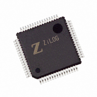
Z8F4822AR020EC Zilog, Z8F4822AR020EC Datasheet - Page 168

Z8F4822AR020EC
Manufacturer Part Number
Z8F4822AR020EC
Description
IC ENCORE MCU FLASH 48K 64LQFP
Manufacturer
Zilog
Series
Encore!® XP®r
Specifications of Z8F4822AR020EC
Core Processor
Z8
Core Size
8-Bit
Speed
20MHz
Connectivity
I²C, IrDA, SPI, UART/USART
Peripherals
Brown-out Detect/Reset, DMA, POR, PWM, WDT
Number Of I /o
46
Program Memory Size
48KB (48K x 8)
Program Memory Type
FLASH
Ram Size
4K x 8
Voltage - Supply (vcc/vdd)
3 V ~ 3.6 V
Data Converters
A/D 12x10b
Oscillator Type
Internal
Operating Temperature
-40°C ~ 105°C
Package / Case
64-LQFP
Lead Free Status / RoHS Status
Contains lead / RoHS non-compliant
Eeprom Size
-
Other names
269-3289
Available stocks
Company
Part Number
Manufacturer
Quantity
Price
- Current page: 168 of 297
- Download datasheet (9Mb)
Table 72. I
PS019921-0308
BITS
FIELD
RESET
R/W
ADDR
Caution:
I
2
C Control Register
2
C Control Register (I2CCTL)
R/W
IEN
7
10B—10-Bit Address
This bit indicates whether a 10- or 7-bit address is being transmitted. After the START bit
is set, if the five most-significant bits of the address are 11110B, this bit is set. When set,
it is reset once the first byte of the address has been sent.
RD—Read
This bit indicates the direction of transfer of the data. It is active high during a read. The
status of this bit is determined by the least-significant bit of the I
START bit is set.
TAS—Transmit Address State
This bit is active high while the address is being shifted out of the I
DSS—Data Shift State
This bit is active high while data is being shifted to or from the I
NCKI—NACK Interrupt
This bit is set high when a Not Acknowledge condition is received or sent and neither the
START nor the STOP bit is active. When set, this bit generates an interrupt that can only
be cleared by setting the START or STOP bit, allowing you to specify whether to perform
a STOP or a repeated START.
The I
action because software cannot tell when the bit is updated by hardware. In the
case of write transactions, the I
cycle if the next transmit data or address byte has not been written (TDRE = 1)
and STOP and START = 0. In this case the ACK bit is not updated until the
transmit interrupt is serviced and the Acknowledge cycle for the previous byte
completes. For examples of how the ACK bit can be used, see
Transaction with a 7-bit Address
with a 10-bit Address
Software must be cautious in making decisions based on this bit within a trans-
2
C Control register
START
R/W1
6
STOP
R/W1
5
(Table
on page 146.
72) enables the I
BIRQ
R/W
2
4
C pauses at the beginning of the Acknowledge
on page 144 and
F52H
0
R/W
TXI
3
2
C operation.
Address Only Transaction
Z8 Encore! XP
R/W1
NAK
2
Product Specification
2
2
C Shift register after the
C Shift register.
Address Only
2
C Shift register.
FLUSH
W1
1
®
F64XX Series
I2C Controller
FILTEN
R/W
0
154
Related parts for Z8F4822AR020EC
Image
Part Number
Description
Manufacturer
Datasheet
Request
R

Part Number:
Description:
Communication Controllers, ZILOG INTELLIGENT PERIPHERAL CONTROLLER (ZIP)
Manufacturer:
Zilog, Inc.
Datasheet:

Part Number:
Description:
KIT DEV FOR Z8 ENCORE 16K TO 64K
Manufacturer:
Zilog
Datasheet:

Part Number:
Description:
KIT DEV Z8 ENCORE XP 28-PIN
Manufacturer:
Zilog
Datasheet:

Part Number:
Description:
DEV KIT FOR Z8 ENCORE 8K/4K
Manufacturer:
Zilog
Datasheet:

Part Number:
Description:
KIT DEV Z8 ENCORE XP 28-PIN
Manufacturer:
Zilog
Datasheet:

Part Number:
Description:
DEV KIT FOR Z8 ENCORE 4K TO 8K
Manufacturer:
Zilog
Datasheet:

Part Number:
Description:
CMOS Z8 microcontroller. ROM 16 Kbytes, RAM 256 bytes, speed 16 MHz, 32 lines I/O, 3.0V to 5.5V
Manufacturer:
Zilog, Inc.
Datasheet:

Part Number:
Description:
Low-cost microcontroller. 512 bytes ROM, 61 bytes RAM, 8 MHz
Manufacturer:
Zilog, Inc.
Datasheet:

Part Number:
Description:
Z8 4K OTP Microcontroller
Manufacturer:
Zilog, Inc.
Datasheet:

Part Number:
Description:
CMOS SUPER8 ROMLESS MCU
Manufacturer:
Zilog, Inc.
Datasheet:

Part Number:
Description:
SL1866 CMOSZ8 OTP Microcontroller
Manufacturer:
Zilog, Inc.
Datasheet:

Part Number:
Description:
SL1866 CMOSZ8 OTP Microcontroller
Manufacturer:
Zilog, Inc.
Datasheet:

Part Number:
Description:
OTP (KB) = 1, RAM = 125, Speed = 12, I/O = 14, 8-bit Timers = 2, Comm Interfaces Other Features = Por, LV Protect, Voltage = 4.5-5.5V
Manufacturer:
Zilog, Inc.
Datasheet:

Part Number:
Description:
Manufacturer:
Zilog, Inc.
Datasheet:


