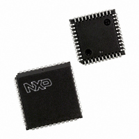
P89LV51RD2FA,512 NXP Semiconductors, P89LV51RD2FA,512 Datasheet - Page 55

P89LV51RD2FA,512
Manufacturer Part Number
P89LV51RD2FA,512
Description
IC 80C51 MCU 1024 RAM 44PLCC
Manufacturer
NXP Semiconductors
Series
89LVr
Datasheet
1.P89LV51RD2BBC557.pdf
(76 pages)
Specifications of P89LV51RD2FA,512
Core Processor
8051
Core Size
8-Bit
Speed
33MHz
Connectivity
SPI, UART/USART
Peripherals
Brown-out Detect/Reset, POR, PWM, WDT
Number Of I /o
32
Program Memory Size
64KB (64K x 8)
Program Memory Type
FLASH
Ram Size
1K x 8
Voltage - Supply (vcc/vdd)
2.7 V ~ 3.6 V
Oscillator Type
Internal
Operating Temperature
-40°C ~ 85°C
Package / Case
44-PLCC
Processor Series
P89LV5x
Core
80C51
Data Bus Width
8 bit
Data Ram Size
1 KB
Interface Type
SPI, UART
Maximum Clock Frequency
33 MHz
Number Of Programmable I/os
32
Number Of Timers
3
Operating Supply Voltage
2.4 V to 3.6 V
Maximum Operating Temperature
+ 85 C
Mounting Style
SMD/SMT
3rd Party Development Tools
PK51, CA51, A51, ULINK2
Minimum Operating Temperature
- 40 C
Package
44PLCC
Device Core
80C51
Family Name
89LV
Maximum Speed
40 MHz
For Use With
622-1017 - BOARD 44-ZIF PLCC SOCKET622-1008 - BOARD FOR LPC9103 10-HVSON
Lead Free Status / RoHS Status
Lead free / RoHS Compliant
Eeprom Size
-
Data Converters
-
Lead Free Status / Rohs Status
Details
Other names
935274176512
P89LV51RD2FA
P89LV51RD2FA
P89LV51RD2FA
P89LV51RD2FA
Available stocks
Company
Part Number
Manufacturer
Quantity
Price
Company:
Part Number:
P89LV51RD2FA,512
Manufacturer:
NXP Semiconductors
Quantity:
10 000
Part Number:
P89LV51RD2FA,512
Manufacturer:
NXP/恩智浦
Quantity:
20 000
NXP Semiconductors
Table 43.
P89LV51RB2_RC2_RD2_5
Product data sheet
Description
External
interrupt 0
Brownout
T0
External
interrupt 1
T1
PCA
UART/SPI
T2
Interrupt polling sequence
6.10 Security bit
6.11 Interrupt priority and polling sequence
Interrupt flag
IE0
-
TF0
IE1
TF1
CF/CCFn
TI/RI/SPIF
TF2, EXF2
The Security Bit protects against software piracy and prevents the contents of the flash
from being read by unauthorized parties in Parallel Programmer mode. It also protects
against code corruption resulting from accidental erasing and programming to the internal
flash memory.
When the Security Bit is activated, all parallel programming commands except for
Chip-Erase are ignored (thus the device cannot be read). However, ISP reading, writing,
or erasing of the user’s code can still be performed if the serial number and length has not
been programmed. Therefore, when a user requests to program the Security Bit, the
programmer should prompt the user and program a serial number into the device.
The device supports eight interrupt sources under a four level priority scheme.
summarizes the polling sequence of the supported interrupts. Note that the SPI serial
interface and the UART share the same interrupt vector. (See
Vector address Interrupt
0003H
004BH
000BH
0013H
001BH
0033H
0023H
002BH
Rev. 05 — 15 December 2009
enable bit
EX0
EBO
ET0
EX1
ET1
EC
ES
ET2
P89LV51RB2/RC2/RD2
Interrupt
priority bit
PX0/H
PBO/H
PT0/H
PX1/H
PT1/H
PPCH
PS/H
PT2/H
8-bit microcontrollers with 80C51 core
Service
priority
1 (highest)
2
3
4
5
6
7
8
Figure
26).
© NXP B.V. 2009. All rights reserved.
Wake-up
power-down
yes
no
no
yes
no
no
no
no
Table 43
55 of 76


