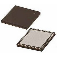
PIC24FJ256GB206-I/MR Microchip Technology, PIC24FJ256GB206-I/MR Datasheet - Page 16

PIC24FJ256GB206-I/MR
Manufacturer Part Number
PIC24FJ256GB206-I/MR
Description
MCU PIC 16BIT FLASH 256K 64VQFN
Manufacturer
Microchip Technology
Series
PIC® 24Fr
Specifications of PIC24FJ256GB206-I/MR
Core Size
16-Bit
Program Memory Size
256KB (85.5K x 24)
Core Processor
PIC
Speed
32MHz
Connectivity
I²C, IrDA, SPI, UART/USART, USB OTG
Peripherals
Brown-out Detect/Reset, LVD, POR, PWM, WDT
Number Of I /o
52
Program Memory Type
FLASH
Ram Size
96K x 8
Voltage - Supply (vcc/vdd)
2.2 V ~ 3.6 V
Data Converters
A/D 16x10b
Oscillator Type
Internal
Operating Temperature
-40°C ~ 85°C
Package / Case
64-VFQFN, Exposed Pad
Controller Family/series
PIC24
No. Of I/o's
52
Ram Memory Size
96KB
Cpu Speed
32MHz
No. Of Timers
5
No. Of Pwm Channels
9
Processor Series
PIC24FJ
Core
PIC
Data Bus Width
16 bit
Data Ram Size
96 KB
Interface Type
I2C, SPI, UART
Maximum Clock Frequency
32 MHz
Number Of Programmable I/os
29
Number Of Timers
5
Operating Supply Voltage
2.2 V to 3.6 V
Maximum Operating Temperature
+ 85 C
Mounting Style
SMD/SMT
3rd Party Development Tools
52713-733, 52714-737, 53276-922, EWDSPIC
Development Tools By Supplier
PG164130, DV164035, DV244005, DV164005, DM240001, MA240021
Minimum Operating Temperature
- 40 C
On-chip Adc
10 bit, 16 Channel
Lead Free Status / RoHS Status
Lead free / RoHS Compliant
Eeprom Size
-
Lead Free Status / Rohs Status
Details
- Current page: 16 of 386
- Download datasheet (4Mb)
PIC24FJ256GB210 FAMILY
1.2
The USB On-The-Go (USB OTG) module provides
on-chip functionality as a target device, compatible with
the USB 2.0 standard, as well as limited stand-alone
functionality as a USB embedded host. By implement-
ing USB Host Negotiation Protocol (HNP), the module
can also dynamically switch between device and host
operation, allowing for a much wider range of versatile
USB enabled applications on a microcontroller
platform.
In
PIC24FJ256GB210 family devices provide a true
single chip USB solution, including an on-chip
transceiver and voltage regulator, and a voltage boost
generator for sourcing bus power during host
operations.
1.3
• Peripheral Pin Select: The Peripheral Pin Select
• Communications: The PIC24FJ256GB210 family
• Analog Features: All members of the
• CTMU Interface: In addition to their other analog
DS39975A-page 16
(PPS) feature allows most digital peripherals to be
mapped over a fixed set of digital I/O pins. Users
may independently map the input and/or output of
any one of the many digital peripherals to any one
of the I/O pins.
incorporates a range of serial communication
peripherals to handle a range of application
requirements. There are three independent I
modules that support both Master and Slave
modes of operation. Devices also have, through
the PPS feature, four independent UARTs with
built-in IrDA
modules.
PIC24FJ256GB210 family include a 10-bit A/D
Converter (ADC) module and a triple comparator
module. The ADC module incorporates program-
mable acquisition time, allowing for a channel to
be selected and a conversion to be initiated
without waiting for a sampling period, and faster
sampling speeds. The comparator module
includes three analog comparators that are
configurable for a wide range of operations.
features, members of the PIC24FJ256GB210
family include the CTMU interface module. This
provides a convenient method for precision time
measurement and pulse generation, and can
serve as an interface for capacitive sensors.
addition
USB On-The-Go
Other Special Features
®
encoders/decoders and three SPI
to
USB
host
functionality,
2
C™
• Enhanced Parallel Master/Parallel Slave Port:
• Real-Time Clock and Calendar: (RTCC) This
1.4
Devices in the PIC24FJ256GB210 family are available
in 64-pin and 100-pin packages. The general block
diagram for all devices is shown in Figure 1-1.
The devices are differentiated from each other in seven
ways:
1.
2.
3.
4.
5.
All other features for devices in this family are identical.
These are summarized in Table 1-1 and Table 1-2.
A
PIC24FJ256GB210 family devices, sorted by function,
is shown in Table 1-1. Note that this table shows the pin
location of individual peripheral features and not how
they are multiplexed on the same pin. This information
is provided in the pinout diagrams in the beginning of
the data sheet. Multiplexed features are sorted by the
priority given to a feature, with the highest priority
peripheral being listed first.
There are general purpose I/O ports, which can
be configured for parallel data communications. In
this mode, the device can be master or slave on
the communication bus. 4-bit, 8-bit and 16-bit data
transfers, with up to 23 external address lines, are
supported in Master modes.
module implements a full-featured clock and
calendar with alarm functions in hardware, freeing
up timer resources and program memory space
for use of the core application.
list
Flash program memory (128 Kbytes for
PIC24FJ128GB2XX devices and 256 Kbytes
for PIC24FJ256GB2XX devices).
Available I/O pins and ports (52 pins on 6 ports
for PIC24FJXXXGB2XX devices and 84 pins on
7 ports for PIC24FJXXXGB2XX devices).
Available Interrupt-on-Change Notification (ICN)
inputs (52 on PIC24FJXXXGB2XX devices and
84 on PIC24FJXXXGB2XX devices).
Available
PIC24FJXXXGB2XX devices and 44 pins on
PIC24FJXXXGB2XX devices).
Analog channels for ADC (16 channels for
PIC24FJXXXGB206 devices and 24 channels
for PIC24FJXXXGB2XX devices).
Details on Individual Family
Members
of
the
remappable
pin
2010 Microchip Technology Inc.
features
pins
available
(29
pins
on
on
the
Related parts for PIC24FJ256GB206-I/MR
Image
Part Number
Description
Manufacturer
Datasheet
Request
R

Part Number:
Description:
Manufacturer:
Microchip Technology Inc.
Datasheet:

Part Number:
Description:
Manufacturer:
Microchip Technology Inc.
Datasheet:

Part Number:
Description:
Manufacturer:
Microchip Technology Inc.
Datasheet:

Part Number:
Description:
Manufacturer:
Microchip Technology Inc.
Datasheet:

Part Number:
Description:
Manufacturer:
Microchip Technology Inc.
Datasheet:

Part Number:
Description:
Manufacturer:
Microchip Technology Inc.
Datasheet:

Part Number:
Description:
Manufacturer:
Microchip Technology Inc.
Datasheet:

Part Number:
Description:
Manufacturer:
Microchip Technology Inc.
Datasheet:


