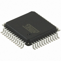
AT32UC3B164-AUT Atmel, AT32UC3B164-AUT Datasheet - Page 228

AT32UC3B164-AUT
Manufacturer Part Number
AT32UC3B164-AUT
Description
IC MCU AVR32 64KB FLASH 48-TQFP
Manufacturer
Atmel
Series
AVR®32 UC3r
Specifications of AT32UC3B164-AUT
Core Processor
AVR
Core Size
32-Bit
Speed
60MHz
Connectivity
I²C, IrDA, SPI, SSC, UART/USART, USB
Peripherals
Brown-out Detect/Reset, DMA, POR, PWM, WDT
Number Of I /o
28
Program Memory Size
64KB (64K x 8)
Program Memory Type
FLASH
Ram Size
16K x 8
Voltage - Supply (vcc/vdd)
1.65 V ~ 1.95 V
Data Converters
A/D 6x10b
Oscillator Type
Internal
Operating Temperature
-40°C ~ 85°C
Package / Case
48-TQFP, 48-VQFP
Controller Family/series
AT32UC3B
No. Of I/o's
28
Ram Memory Size
16KB
Cpu Speed
60MHz
No. Of Timers
1
Rohs Compliant
Yes
For Use With
ATSTK600-TQFP48 - STK600 SOCKET/ADAPTER 48-TQFPATAVRONEKIT - KIT AVR/AVR32 DEBUGGER/PROGRMMR770-1008 - ISP 4PORT ATMEL AVR32 MCU SPIATEVK1101 - KIT DEV/EVAL FOR AVR32 AT32UC3B
Lead Free Status / RoHS Status
Lead free / RoHS Compliant
Eeprom Size
-
Available stocks
Company
Part Number
Manufacturer
Quantity
Price
- Current page: 228 of 676
- Download datasheet (11Mb)
19.10.6.2
Figure 19-13. Internal Address Usage
19.11 Using the Peripheral DMA Controller
19.11.1
19.11.2
32059I–06/2010
Data Transmit with the Peripheral DMA Controller
Data Receive with the Peripheral DMA Controller
10-bit Slave Addressing
For a slave address higher than 7 bits, the user must configure the address size (IADRSZ) and
set the other slave address bits in the internal address register (IADR). The two remaining Inter-
nal address bytes, IADR[15:8] and IADR[23:16] can be used the same as in 7-bit Slave
Addressing.
Example: Address a 10-bit device:
(10-bit device address is b1 b2 b3 b4 b5 b6 b7 b8 b9 b10)
1. Program IADRSZ = 1,
2. Program DADR with 1 1 1 1 0 b1 b2 (b1 is the MSB of the 10-bit address, b2, etc.)
3. Program IADR with b3 b4 b5 b6 b7 b8 b9 b10 (b10 is the LSB of the 10-bit address)
Figure 19-13
the use of internal addresses to access the device.
The use of the Peripheral DMA Controller significantly reduces the CPU load.
To assure correct implementation, respect the following programming sequences:
1. Initialize the Peripheral DMA Controller TX channel (memory pointers, size, etc.).
2. Configure the master mode (DADR, CKDIV, etc.).
3. Start the transfer by setting the Peripheral DMA Controller TXEN bit.
4. Wait for the Peripheral DMA Controller end TX flag.
5. Disable the Peripheral DMA Controller by setting the Peripheral DMA Controller TXDIS
1. Initialize the Peripheral DMA Controller TX channel (memory pointers, size, etc.).
2. Configure the master mode (DADR, CKDIV, etc.).
3. Start the transfer by setting the Peripheral DMA Controller RXEN bit.
4. Wait for the Peripheral DMA Controller end RX flag.
S
T
A
R
T
M
S
B
bit.
Address
Device
0
below shows a byte write to an Atmel AT24LC512 EEPROM. This demonstrates
S
B
L
W
W
R
E
T
R
I
/
A
C
K
WORD ADDRESS
M
S
B
FIRST
A
C
K
WORD ADDRESS
SECOND
L
S
B
A
C
K
DATA
A
C
K
S
O
P
T
AT32UC3B
228
Related parts for AT32UC3B164-AUT
Image
Part Number
Description
Manufacturer
Datasheet
Request
R

Part Number:
Description:
DEV KIT FOR AVR/AVR32
Manufacturer:
Atmel
Datasheet:

Part Number:
Description:
INTERVAL AND WIPE/WASH WIPER CONTROL IC WITH DELAY
Manufacturer:
ATMEL Corporation
Datasheet:

Part Number:
Description:
Low-Voltage Voice-Switched IC for Hands-Free Operation
Manufacturer:
ATMEL Corporation
Datasheet:

Part Number:
Description:
MONOLITHIC INTEGRATED FEATUREPHONE CIRCUIT
Manufacturer:
ATMEL Corporation
Datasheet:

Part Number:
Description:
AM-FM Receiver IC U4255BM-M
Manufacturer:
ATMEL Corporation
Datasheet:

Part Number:
Description:
Monolithic Integrated Feature Phone Circuit
Manufacturer:
ATMEL Corporation
Datasheet:

Part Number:
Description:
Multistandard Video-IF and Quasi Parallel Sound Processing
Manufacturer:
ATMEL Corporation
Datasheet:

Part Number:
Description:
High-performance EE PLD
Manufacturer:
ATMEL Corporation
Datasheet:

Part Number:
Description:
8-bit Flash Microcontroller
Manufacturer:
ATMEL Corporation
Datasheet:

Part Number:
Description:
2-Wire Serial EEPROM
Manufacturer:
ATMEL Corporation
Datasheet:


