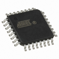
ATTINY28L-4AU Atmel, ATTINY28L-4AU Datasheet - Page 79

ATTINY28L-4AU
Manufacturer Part Number
ATTINY28L-4AU
Description
IC MCU AVR 2K FLASH 4MHZ 32-TQFP
Manufacturer
Atmel
Series
AVR® ATtinyr
Specifications of ATTINY28L-4AU
Core Processor
AVR
Core Size
8-Bit
Speed
4MHz
Peripherals
POR, WDT
Number Of I /o
11
Program Memory Size
2KB (1K x 16)
Program Memory Type
FLASH
Voltage - Supply (vcc/vdd)
2.7 V ~ 5.5 V
Oscillator Type
Internal
Operating Temperature
-40°C ~ 85°C
Package / Case
32-TQFP, 32-VQFP
Processor Series
ATTINY2x
Core
AVR8
Data Bus Width
8 bit
Data Ram Size
32 B
Maximum Clock Frequency
4 MHz
Number Of Programmable I/os
11
Number Of Timers
1
Maximum Operating Temperature
+ 85 C
Mounting Style
SMD/SMT
3rd Party Development Tools
EWAVR, EWAVR-BL
Development Tools By Supplier
ATAVRDRAGON, ATSTK500, ATSTK600, ATAVRISP2, ATAVRONEKIT
Minimum Operating Temperature
- 40 C
On-chip Adc
8 bit
Package
32TQFP
Device Core
AVR
Family Name
ATtiny
Maximum Speed
4 MHz
Ram Size
32 Byte
Operating Supply Voltage
3.3|5 V
For Use With
ATSTK600-DIP40 - STK600 SOCKET/ADAPTER 40-PDIPATSTK500 - PROGRAMMER AVR STARTER KIT
Lead Free Status / RoHS Status
Lead free / RoHS Compliant
Eeprom Size
-
Ram Size
-
Data Converters
-
Connectivity
-
Lead Free Status / Rohs Status
Details
Available stocks
Company
Part Number
Manufacturer
Quantity
Price
Table of Contents
1062F–AVR–07/06
Features................................................................................................. 1
Pin Configurations................................................................................ 1
Description ............................................................................................ 2
Architectural Overview......................................................................... 6
Timer/Counter0 ................................................................................... 24
Watchdog Timer.................................................................................. 27
Calibrated Internal RC Oscillator ...................................................... 29
Hardware Modulator ........................................................................... 30
Analog Comparator ............................................................................ 35
I/O Ports............................................................................................... 37
Memory Programming........................................................................ 45
Parallel Programming Characteristics.............................................. 52
Block Diagram ...................................................................................................... 2
Pin Descriptions.................................................................................................... 3
Clock Options ....................................................................................................... 4
General-purpose Register File.............................................................................. 7
ALU – Arithmetic Logic Unit.................................................................................. 7
Downloadable Flash Program Memory ................................................................ 7
Program and Data Addressing Modes.................................................................. 7
Subroutine and Interrupt Hardware Stack .......................................................... 10
Memory Access and Instruction Execution Timing ............................................. 10
I/O Memory ......................................................................................................... 11
Reset and Interrupt Handling.............................................................................. 12
Sleep Modes....................................................................................................... 21
Timer/Counter Prescaler..................................................................................... 24
Port A.................................................................................................................. 37
Port B.................................................................................................................. 40
Port D.................................................................................................................. 43
Program Memory Lock Bits ................................................................................ 45
Fuse Bits............................................................................................................. 45
Signature Bytes .................................................................................................. 45
Calibration Byte .................................................................................................. 45
Programming the Flash ...................................................................................... 45
Parallel Programming ......................................................................................... 46
ATtiny28L/V
i


