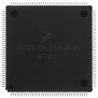
MC9S12H256VFVE Freescale Semiconductor, MC9S12H256VFVE Datasheet - Page 97

MC9S12H256VFVE
Manufacturer Part Number
MC9S12H256VFVE
Description
IC MCU 256K FLASH 16MHZ 144-LQFP
Manufacturer
Freescale Semiconductor
Series
HCS12r
Datasheet
1.MC9S12H256VFVER.pdf
(130 pages)
Specifications of MC9S12H256VFVE
Core Processor
HCS12
Core Size
16-Bit
Speed
16MHz
Connectivity
CAN, I²C, SCI, SPI
Peripherals
LCD, POR, PWM, WDT
Number Of I /o
99
Program Memory Size
256KB (256K x 8)
Program Memory Type
FLASH
Eeprom Size
4K x 8
Ram Size
12K x 8
Voltage - Supply (vcc/vdd)
2.35 V ~ 5.25 V
Data Converters
A/D 16x10b
Oscillator Type
Internal
Operating Temperature
-40°C ~ 105°C
Package / Case
144-LQFP
Processor Series
S12H
Core
HCS12
Data Bus Width
16 bit
Data Ram Size
12 KB
Interface Type
CAN/SCI/SPI
Maximum Clock Frequency
16 MHz
Number Of Programmable I/os
115
Number Of Timers
8
Operating Supply Voltage
- 0.3 V to + 6 V
Maximum Operating Temperature
+ 105 C
Mounting Style
SMD/SMT
3rd Party Development Tools
EWHCS12
Minimum Operating Temperature
- 40 C
On-chip Adc
16-ch x 10-bit
Lead Free Status / RoHS Status
Lead free / RoHS Compliant
Available stocks
Company
Part Number
Manufacturer
Quantity
Price
Company:
Part Number:
MC9S12H256VFVE
Manufacturer:
Freescale Semiconductor
Quantity:
10 000
Company:
Part Number:
MC9S12H256VFVER
Manufacturer:
Freescale
Quantity:
551
Company:
Part Number:
MC9S12H256VFVER
Manufacturer:
Freescale Semiconductor
Quantity:
10 000
A.1.10 Supply Currents
This section describes the current consumption characteristics of the device as well as the conditions for
the measurements.
A.1.10.1 Measurement Conditions
All measurements are without output loads. Unless otherwise noted the currents are measured in single
chip mode, internal voltage regulator enabled and at 16MHz bus frequency using a 4MHz oscillator in
Colpitts mode. Production testing is performed using a square wave signal at the EXTAL input.
A.1.10.2 Additional Remarks
In expanded modes the currents flowing in the system are highly dependent on the load at the address, data
and control signals as well as on the duty cycle of those signals. No generally applicable numbers can be
Conditions are shown in Table A-4 unless otherwise noted
NOTES:
1. Maximum leakage current occurs at maximum operating temperature. Current decreases by approximately one-half for
2. Maximum leakage current occurs at maximum operating temperature. Current decreases by approximately one-half for
3. This only applies to the EPP package, non-EPP packages retain the 100ns typ and 130ns max spec.
4. Refer to Section A.1.4 Current Injection, for more details
5. Parameter only applies in STOP or Pseudo STOP mode.
16
17
18
19
each 8 C to 12 C in the temperature range from 50 C to 125 C.
each 8 C to 12 C in the temperature range from 50 C to 125 C.
D Input Capacitance
T
P Port H, J Interrupt Input Pulse filtered
P Port H, J Interrupt Input Pulse passed
Injection current
Single Pin limit
Total Device Limit. Sum of all injected currents
4
Table A-6 5V I/O Characteristics
5
5
t
t
PULSE
PULSE
I
I
C
ICS
ICP
in
MC9S12H256 Device User Guide — V01.20
–2.5
–25
10
6
–
2.5
25
–
3
mA
pF
s
s
97


