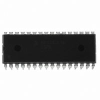
MC908JL16CSPE Freescale Semiconductor, MC908JL16CSPE Datasheet - Page 187

MC908JL16CSPE
Manufacturer Part Number
MC908JL16CSPE
Description
IC MCU 16K FLASH 8MHZ 32-SDIP
Manufacturer
Freescale Semiconductor
Series
HC08r
Datasheet
1.MC908JL16CFJER.pdf
(230 pages)
Specifications of MC908JL16CSPE
Core Processor
HC08
Core Size
8-Bit
Speed
8MHz
Connectivity
I²C, SCI
Peripherals
LED, LVD, POR, PWM
Number Of I /o
26
Program Memory Size
16KB (16K x 8)
Program Memory Type
FLASH
Ram Size
512 x 8
Voltage - Supply (vcc/vdd)
2.7 V ~ 5.5 V
Data Converters
A/D 13x10b
Oscillator Type
Internal
Operating Temperature
-40°C ~ 85°C
Package / Case
32-SDIP (0.400", 10.16mm)
Controller Family/series
HC08
No. Of I/o's
26
Ram Memory Size
512Byte
Cpu Speed
8MHz
No. Of Timers
2
Embedded Interface Type
I2C, SCI
Rohs Compliant
Yes
Processor Series
HC08JL
Core
HC08
Data Bus Width
8 bit
Data Ram Size
512 B
Interface Type
SCI
Maximum Clock Frequency
16 MHz
Number Of Programmable I/os
26
Number Of Timers
4
Operating Supply Voltage
2.7 V to 5.5 V
Maximum Operating Temperature
+ 85 C
Mounting Style
Through Hole
Development Tools By Supplier
FSICEBASE, DEMO908JL16E, M68CBL05CE
Minimum Operating Temperature
- 40 C
On-chip Adc
10 bit, 13 Channel
For Use With
DEMO908JL16E - BOARD DEMO FOR MC908JL16
Lead Free Status / RoHS Status
Lead free / RoHS Compliant
Eeprom Size
-
Lead Free Status / Rohs Status
Details
Available stocks
Company
Part Number
Manufacturer
Quantity
Price
Company:
Part Number:
MC908JL16CSPE
Manufacturer:
SONY
Quantity:
1 560
Part Number:
MC908JL16CSPE
Manufacturer:
FREESCALE
Quantity:
20 000
- Current page: 187 of 230
- Download datasheet (2Mb)
Figure
IRQ = V
Enter monitor mode with the pin configuration shown above by pulling RST low and then high. The rising
edge of RST latches monitor mode. Once monitor mode is latched, the values on the specified pins can
change.
Once out of reset, the MCU waits for the host to send eight security bytes. (See
security bytes, the MCU sends a break signal (10 consecutive logic zeros) to the host, indicating that it is
ready to receive a command. The break signal also provides a timing reference to allow the host to
determine the necessary baud rate.
In monitor mode, the MCU uses different vectors for reset, SWI, and break interrupt. The alternate vectors
are in the $FE page instead of the $FF page and allow code execution from the internal monitor firmware
instead of user code.
Table 16-2
Freescale Semiconductor
16-9. shows a simplified diagram of the monitor mode entry when the reset vector is blank and
DD
. An OSC1 frequency of 9.8304MHz is required for a baud rate of 9600.
is a summary of the vector differences between user mode and monitor mode.
Monitor
Modes
Notes:
1. If the high voltage (V
User
COP enable output. The COP is a mask option enabled or disabled by the COPD bit in the
configuration register.
Figure 16-9. Low-Voltage Monitor Mode Entry Flowchart
Disabled
Enabled
COP
Table 16-2. Monitor Mode Vector Differences
(1)
TST
MC68HC908JL16 Data Sheet, Rev. 1.1
) is removed from the IRQ pin or the RST pin, the SIM asserts its
Vector
$FEFE
$FFFE
Reset
High
MONITOR MODE
TRIGGERED?
POR RESET
IS VECTOR
EXECUTE
MONITOR
BLANK?
CODE
POR
YES
YES
Vector
$FEFF
$FFFF
Reset
Low
NO
NO
Functions
Vector
$FFFC
$FEFC
Break
High
NORMAL USER
MODE
Vector
$FFFD
$FEFD
Break
Low
Vector
$FFFC
$FEFC
High
SWI
16.3.8
Monitor Module (MON)
Security.) After the
$FEFD
Vector
$FFFD
Low
SWI
187
Related parts for MC908JL16CSPE
Image
Part Number
Description
Manufacturer
Datasheet
Request
R
Part Number:
Description:
Manufacturer:
Freescale Semiconductor, Inc
Datasheet:
Part Number:
Description:
Manufacturer:
Freescale Semiconductor, Inc
Datasheet:
Part Number:
Description:
Manufacturer:
Freescale Semiconductor, Inc
Datasheet:
Part Number:
Description:
Manufacturer:
Freescale Semiconductor, Inc
Datasheet:
Part Number:
Description:
Manufacturer:
Freescale Semiconductor, Inc
Datasheet:
Part Number:
Description:
Manufacturer:
Freescale Semiconductor, Inc
Datasheet:
Part Number:
Description:
Manufacturer:
Freescale Semiconductor, Inc
Datasheet:
Part Number:
Description:
Manufacturer:
Freescale Semiconductor, Inc
Datasheet:
Part Number:
Description:
Manufacturer:
Freescale Semiconductor, Inc
Datasheet:
Part Number:
Description:
Manufacturer:
Freescale Semiconductor, Inc
Datasheet:
Part Number:
Description:
Manufacturer:
Freescale Semiconductor, Inc
Datasheet:
Part Number:
Description:
Manufacturer:
Freescale Semiconductor, Inc
Datasheet:
Part Number:
Description:
Manufacturer:
Freescale Semiconductor, Inc
Datasheet:
Part Number:
Description:
Manufacturer:
Freescale Semiconductor, Inc
Datasheet:
Part Number:
Description:
Manufacturer:
Freescale Semiconductor, Inc
Datasheet:


