MC908JL16CSPE Freescale Semiconductor, MC908JL16CSPE Datasheet - Page 112
MC908JL16CSPE
Manufacturer Part Number
MC908JL16CSPE
Description
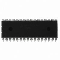
IC MCU 16K FLASH 8MHZ 32-SDIP
Manufacturer
Freescale Semiconductor
Series
HC08r
Datasheet
1.MC908JL16CFJER.pdf
(230 pages)
Specifications of MC908JL16CSPE
Core Processor
HC08
Core Size
8-Bit
Speed
8MHz
Connectivity
I²C, SCI
Peripherals
LED, LVD, POR, PWM
Number Of I /o
26
Program Memory Size
16KB (16K x 8)
Program Memory Type
FLASH
Ram Size
512 x 8
Voltage - Supply (vcc/vdd)
2.7 V ~ 5.5 V
Data Converters
A/D 13x10b
Oscillator Type
Internal
Operating Temperature
-40°C ~ 85°C
Package / Case
32-SDIP (0.400", 10.16mm)
Controller Family/series
HC08
No. Of I/o's
26
Ram Memory Size
512Byte
Cpu Speed
8MHz
No. Of Timers
2
Embedded Interface Type
I2C, SCI
Rohs Compliant
Yes
Processor Series
HC08JL
Core
HC08
Data Bus Width
8 bit
Data Ram Size
512 B
Interface Type
SCI
Maximum Clock Frequency
16 MHz
Number Of Programmable I/os
26
Number Of Timers
4
Operating Supply Voltage
2.7 V to 5.5 V
Maximum Operating Temperature
+ 85 C
Mounting Style
Through Hole
Development Tools By Supplier
FSICEBASE, DEMO908JL16E, M68CBL05CE
Minimum Operating Temperature
- 40 C
On-chip Adc
10 bit, 13 Channel
For Use With
DEMO908JL16E - BOARD DEMO FOR MC908JL16
Lead Free Status / RoHS Status
Lead free / RoHS Compliant
Eeprom Size
-
Lead Free Status / Rohs Status
Details
Available stocks
Company
Part Number
Manufacturer
Quantity
Price
Company:

Part Number:
MC908JL16CSPE
Manufacturer:
SONY
Quantity:
1 560
Part Number:
MC908JL16CSPE
Manufacturer:
FREESCALE
Quantity:
20 000


Multi-Master IIC Interface (MMIIC)
8.4.3 Slave Address Transmission
The first byte of data transfer immediately after the START signal is the slave address transmitted by the
master. This is a seven-bit calling address followed by a R/W bit. The R/W bit tells the slave the desired
direction of data transfer.
Only the slave with a calling address that matches the one transmitted by the master will respond by
sending back an acknowledge bit. This is done by pulling the SDA low at the 9th clock (see
No two slaves in the system may have the same address. If the IIC is master and it transmits an address
that is equal to its own slave address an interrupt flag is set. The IIC cannot be master and slave at the
same time. However, if arbitration is lost during an address cycle the IIC will revert to slave mode and
operate correctly even if it is being addressed by another master.
8.4.4 Data Transfer
Once successful slave addressing is achieved, the data transfer can proceed byte-by-byte in a direction
specified by the R/W bit sent by the calling master.
All transfers that come after an address cycle are referred to as data transfers, even if they carry
sub-address information for the slave device
Each data byte is 8 bits long. Data may be changed only while SCL is low and must be held stable while
SCL is high as shown in
transferred first. Each data byte is followed by a 9th (acknowledge) bit, which is signalled from the
receiving device. An acknowledge is signalled by pulling the SDA low at the ninth clock. In summary, one
complete data transfer needs nine clock pulses.
If the slave receiver does not acknowledge the master in the 9th bit time, the SDA line must be left high
by the slave. The master interprets the failed acknowledge as an unsuccessful data transfer.
If the master receiver does not acknowledge the slave transmitter after a data byte transmission, the slave
interprets this as an end of data transfer and releases the SDA line.
In either case, the data transfer is aborted and the master does one of two things:
8.4.5 STOP Signal
The master can terminate the communication by generating a STOP signal to free the bus. However, the
master may generate a START signal followed by a calling command without generating a STOP signal
first. This is called repeated START. A STOP signal is defined as a low-to-high transition of SDA while
SCL at logical “1” (see
The master can generate a STOP even if the slave has generated an acknowledge at which point the
slave must release the bus.
112
•
•
1 = Read transfer, the slave transmits data to the master.
0 = Write transfer, the master transmits data to the slave.
Relinquishes the bus by generating a STOP signal.
Commences a new calling by generating a repeated START signal.
Figure
Figure
8-2).
8-2. There is one clock pulse on SCL for each data bit, the MSB being
MC68HC908JL16 Data Sheet, Rev. 1.1
Freescale Semiconductor
Figure
8-2).
Related parts for MC908JL16CSPE
Image
Part Number
Description
Manufacturer
Datasheet
Request
R

Part Number:
Description:
Manufacturer:
Freescale Semiconductor, Inc
Datasheet:
Part Number:
Description:
Manufacturer:
Freescale Semiconductor, Inc
Datasheet:
Part Number:
Description:
Manufacturer:
Freescale Semiconductor, Inc
Datasheet:
Part Number:
Description:
Manufacturer:
Freescale Semiconductor, Inc
Datasheet:
Part Number:
Description:
Manufacturer:
Freescale Semiconductor, Inc
Datasheet:
Part Number:
Description:
Manufacturer:
Freescale Semiconductor, Inc
Datasheet:
Part Number:
Description:
Manufacturer:
Freescale Semiconductor, Inc
Datasheet:
Part Number:
Description:
Manufacturer:
Freescale Semiconductor, Inc
Datasheet:
Part Number:
Description:
Manufacturer:
Freescale Semiconductor, Inc
Datasheet:
Part Number:
Description:
Manufacturer:
Freescale Semiconductor, Inc
Datasheet:
Part Number:
Description:
Manufacturer:
Freescale Semiconductor, Inc
Datasheet:
Part Number:
Description:
Manufacturer:
Freescale Semiconductor, Inc
Datasheet:
Part Number:
Description:
Manufacturer:
Freescale Semiconductor, Inc
Datasheet:
Part Number:
Description:
Manufacturer:
Freescale Semiconductor, Inc
Datasheet:
Part Number:
Description:
Manufacturer:
Freescale Semiconductor, Inc
Datasheet: