MC908JL16CSPE Freescale Semiconductor, MC908JL16CSPE Datasheet - Page 166
MC908JL16CSPE
Manufacturer Part Number
MC908JL16CSPE
Description
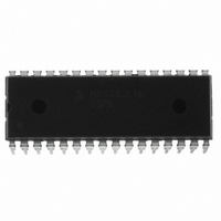
IC MCU 16K FLASH 8MHZ 32-SDIP
Manufacturer
Freescale Semiconductor
Series
HC08r
Datasheet
1.MC908JL16CFJER.pdf
(230 pages)
Specifications of MC908JL16CSPE
Core Processor
HC08
Core Size
8-Bit
Speed
8MHz
Connectivity
I²C, SCI
Peripherals
LED, LVD, POR, PWM
Number Of I /o
26
Program Memory Size
16KB (16K x 8)
Program Memory Type
FLASH
Ram Size
512 x 8
Voltage - Supply (vcc/vdd)
2.7 V ~ 5.5 V
Data Converters
A/D 13x10b
Oscillator Type
Internal
Operating Temperature
-40°C ~ 85°C
Package / Case
32-SDIP (0.400", 10.16mm)
Controller Family/series
HC08
No. Of I/o's
26
Ram Memory Size
512Byte
Cpu Speed
8MHz
No. Of Timers
2
Embedded Interface Type
I2C, SCI
Rohs Compliant
Yes
Processor Series
HC08JL
Core
HC08
Data Bus Width
8 bit
Data Ram Size
512 B
Interface Type
SCI
Maximum Clock Frequency
16 MHz
Number Of Programmable I/os
26
Number Of Timers
4
Operating Supply Voltage
2.7 V to 5.5 V
Maximum Operating Temperature
+ 85 C
Mounting Style
Through Hole
Development Tools By Supplier
FSICEBASE, DEMO908JL16E, M68CBL05CE
Minimum Operating Temperature
- 40 C
On-chip Adc
10 bit, 13 Channel
For Use With
DEMO908JL16E - BOARD DEMO FOR MC908JL16
Lead Free Status / RoHS Status
Lead free / RoHS Compliant
Eeprom Size
-
Lead Free Status / Rohs Status
Details
Available stocks
Company
Part Number
Manufacturer
Quantity
Price
Company:

Part Number:
MC908JL16CSPE
Manufacturer:
SONY
Quantity:
1 560
Part Number:
MC908JL16CSPE
Manufacturer:
FREESCALE
Quantity:
20 000


Low-Voltage Inhibit (LVI)
14.4 LVI Control Register (CONFIG2/CONFIG1)
The LVI module is controlled by three bits in the configuration registers, CONFIG1 and CONFIG2.
LVID — Low Voltage Inhibit Disable Bit
LVIT1, LVIT0 — LVI Trip Voltage Selection Bits
14.5 Low-Power Modes
The STOP and WAIT instructions put the MCU in low power-consumption standby modes.
14.5.1 Wait Mode
The LVI module, when enabled, will continue to operate in wait mode.
14.5.2 Stop Mode
The LVI module, when enabled, will continue to operate in stop mode.
166
LVID disables the LVI module. Reset clears LVID.
These two bits determine at which level of V
are cleared by a power-on reset only.
1 = Low voltage inhibit disabled
0 = Low voltage inhibit enabled
Address: $001E
Address: $001F
Reset:
Reset:
Read:
Read:
Write:
Write:
POR:
IRQPUD
COPRS
Bit 7
Bit 7
R
R
0
0
0
1. See
Figure 14-2. Configuration Register 2 (CONFIG2)
Figure 14-3. Configuration Register 1 (CONFIG1)
LVIT1
= Reserved
= Reserved
0
0
1
1
Chapter 17 Electrical Specifications
R
R
6
0
0
6
0
Table 14-1. Trip Voltage Selection
MC68HC908JL16 Data Sheet, Rev. 1.1
R
R
5
0
0
5
0
LVIT0
0
1
0
1
DD
U = Unaffected
the LVI module will come into action. LVIT1 and LVIT0
LVIT1
LVID
U
4
0
4
0
For V
For V
For V
LVIT0
U
R
3
0
3
0
Comments
for full parameters.
DD
DD
DD
Reserved
= 3 V operation
= 3 V operation
= 5 V operation
SSREC
R
2
0
0
2
0
(1)
STOP
R
1
0
0
1
0
Freescale Semiconductor
ICLKDIS
STOP_
COPD
Bit 0
Bit 0
0
0
0
Related parts for MC908JL16CSPE
Image
Part Number
Description
Manufacturer
Datasheet
Request
R

Part Number:
Description:
Manufacturer:
Freescale Semiconductor, Inc
Datasheet:
Part Number:
Description:
Manufacturer:
Freescale Semiconductor, Inc
Datasheet:
Part Number:
Description:
Manufacturer:
Freescale Semiconductor, Inc
Datasheet:
Part Number:
Description:
Manufacturer:
Freescale Semiconductor, Inc
Datasheet:
Part Number:
Description:
Manufacturer:
Freescale Semiconductor, Inc
Datasheet:
Part Number:
Description:
Manufacturer:
Freescale Semiconductor, Inc
Datasheet:
Part Number:
Description:
Manufacturer:
Freescale Semiconductor, Inc
Datasheet:
Part Number:
Description:
Manufacturer:
Freescale Semiconductor, Inc
Datasheet:
Part Number:
Description:
Manufacturer:
Freescale Semiconductor, Inc
Datasheet:
Part Number:
Description:
Manufacturer:
Freescale Semiconductor, Inc
Datasheet:
Part Number:
Description:
Manufacturer:
Freescale Semiconductor, Inc
Datasheet:
Part Number:
Description:
Manufacturer:
Freescale Semiconductor, Inc
Datasheet:
Part Number:
Description:
Manufacturer:
Freescale Semiconductor, Inc
Datasheet:
Part Number:
Description:
Manufacturer:
Freescale Semiconductor, Inc
Datasheet:
Part Number:
Description:
Manufacturer:
Freescale Semiconductor, Inc
Datasheet: