MC908JL16CSPE Freescale Semiconductor, MC908JL16CSPE Datasheet - Page 109
MC908JL16CSPE
Manufacturer Part Number
MC908JL16CSPE
Description
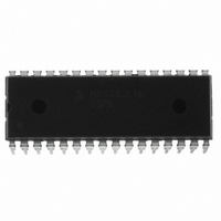
IC MCU 16K FLASH 8MHZ 32-SDIP
Manufacturer
Freescale Semiconductor
Series
HC08r
Datasheet
1.MC908JL16CFJER.pdf
(230 pages)
Specifications of MC908JL16CSPE
Core Processor
HC08
Core Size
8-Bit
Speed
8MHz
Connectivity
I²C, SCI
Peripherals
LED, LVD, POR, PWM
Number Of I /o
26
Program Memory Size
16KB (16K x 8)
Program Memory Type
FLASH
Ram Size
512 x 8
Voltage - Supply (vcc/vdd)
2.7 V ~ 5.5 V
Data Converters
A/D 13x10b
Oscillator Type
Internal
Operating Temperature
-40°C ~ 85°C
Package / Case
32-SDIP (0.400", 10.16mm)
Controller Family/series
HC08
No. Of I/o's
26
Ram Memory Size
512Byte
Cpu Speed
8MHz
No. Of Timers
2
Embedded Interface Type
I2C, SCI
Rohs Compliant
Yes
Processor Series
HC08JL
Core
HC08
Data Bus Width
8 bit
Data Ram Size
512 B
Interface Type
SCI
Maximum Clock Frequency
16 MHz
Number Of Programmable I/os
26
Number Of Timers
4
Operating Supply Voltage
2.7 V to 5.5 V
Maximum Operating Temperature
+ 85 C
Mounting Style
Through Hole
Development Tools By Supplier
FSICEBASE, DEMO908JL16E, M68CBL05CE
Minimum Operating Temperature
- 40 C
On-chip Adc
10 bit, 13 Channel
For Use With
DEMO908JL16E - BOARD DEMO FOR MC908JL16
Lead Free Status / RoHS Status
Lead free / RoHS Compliant
Eeprom Size
-
Lead Free Status / Rohs Status
Details
Available stocks
Company
Part Number
Manufacturer
Quantity
Price
Company:

Part Number:
MC908JL16CSPE
Manufacturer:
SONY
Quantity:
1 560
Part Number:
MC908JL16CSPE
Manufacturer:
FREESCALE
Quantity:
20 000


Chapter 8
Multi-Master IIC Interface (MMIIC)
8.1 Introduction
The Multi-master IIC (MMIIC) Interface is designed for internal serial communication between the MCU
and other IIC devices. A hardware circuit generates “start” and “stop” signal, while byte by byte data
transfer is interrupt driven by the software algorithm. Therefore, it can greatly help the software in dealing
with other devices to have higher system efficiency in a typical digital monitor system.
The MMIIC not only can be applied in internal communications, but can also be used as a typical
command reception serial bus for factory setup and alignment purposes. It also provides the flexibility of
hooking additional devices to an existing system for future expansion without adding extra hardware.
This Multi-master IIC module uses the SCL clock line and the SDA data line to communicate with external
DDC host or IIC interface. These two pins are user selectable using the CONFIG2 register (see
Figure 3-3. Configuration Register 2
their application needs.
The maximum data rate typically is 400k-bps. The maximum communication length and the number of
devices that can be connected are limited by a maximum bus capacitance of 400pF.
8.2 Features
Freescale Semiconductor
•
•
•
•
•
•
•
•
•
•
Compatibility with multi-master IIC bus standard
Software controllable acknowledge bit generation
Interrupt driven byte by byte data transfer
Calling address identification interrupt
Auto detection of R/W bit and switching of transmit or receive mode
Detection of START, repeated START, and STOP signals
Auto generation of START and STOP condition in master mode
Arbitration loss detection and No-ACK awareness in master mode
8 selectable baud rate master clocks
Automatic recognition of the received acknowledge bit
The outputs of SCL and SDA pins are open-drain type, these pins contain
ESD clamping diodes to V
V
DD
+ 0.3 V.
MC68HC908JL16 Data Sheet, Rev. 1.1
(CONFIG2)) to share either PTA2/PTA3 or PTD6/PTD7 based on
DD
and therefore cannot be driven to higher than
NOTE
109
Related parts for MC908JL16CSPE
Image
Part Number
Description
Manufacturer
Datasheet
Request
R

Part Number:
Description:
Manufacturer:
Freescale Semiconductor, Inc
Datasheet:
Part Number:
Description:
Manufacturer:
Freescale Semiconductor, Inc
Datasheet:
Part Number:
Description:
Manufacturer:
Freescale Semiconductor, Inc
Datasheet:
Part Number:
Description:
Manufacturer:
Freescale Semiconductor, Inc
Datasheet:
Part Number:
Description:
Manufacturer:
Freescale Semiconductor, Inc
Datasheet:
Part Number:
Description:
Manufacturer:
Freescale Semiconductor, Inc
Datasheet:
Part Number:
Description:
Manufacturer:
Freescale Semiconductor, Inc
Datasheet:
Part Number:
Description:
Manufacturer:
Freescale Semiconductor, Inc
Datasheet:
Part Number:
Description:
Manufacturer:
Freescale Semiconductor, Inc
Datasheet:
Part Number:
Description:
Manufacturer:
Freescale Semiconductor, Inc
Datasheet:
Part Number:
Description:
Manufacturer:
Freescale Semiconductor, Inc
Datasheet:
Part Number:
Description:
Manufacturer:
Freescale Semiconductor, Inc
Datasheet:
Part Number:
Description:
Manufacturer:
Freescale Semiconductor, Inc
Datasheet:
Part Number:
Description:
Manufacturer:
Freescale Semiconductor, Inc
Datasheet:
Part Number:
Description:
Manufacturer:
Freescale Semiconductor, Inc
Datasheet: