PIC12CE519/JW Microchip Technology, PIC12CE519/JW Datasheet - Page 115
PIC12CE519/JW
Manufacturer Part Number
PIC12CE519/JW
Description
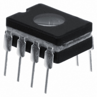
IC MCU EPROM 1KX12 W/EE 8CDIP
Manufacturer
Microchip Technology
Series
PIC® 12Cr
Datasheets
1.PIC16F688T-ISL.pdf
(688 pages)
2.PIC12C508A-04SM.pdf
(113 pages)
3.PIC12C508A-04SM.pdf
(4 pages)
4.PIC12CE518-04SM.pdf
(16 pages)
Specifications of PIC12CE519/JW
Core Processor
PIC
Core Size
8-Bit
Speed
4MHz
Peripherals
POR, WDT
Number Of I /o
5
Program Memory Size
1.5KB (1K x 12)
Program Memory Type
EPROM, UV
Eeprom Size
16 x 8
Ram Size
41 x 8
Voltage - Supply (vcc/vdd)
3 V ~ 5.5 V
Oscillator Type
Internal
Operating Temperature
0°C ~ 70°C
Package / Case
8-CDIP (0.300", 7.62mm) Window
For Use With
ISPICR1 - ADAPTER IN-CIRCUIT PROGRAMMINGDVA12XP080 - ADAPTER DEVICE FOR MPLAB-ICEAC124001 - MODULE SKT PROMATEII 8DIP/SOIC
Lead Free Status / RoHS Status
Contains lead / RoHS non-compliant
Data Converters
-
Connectivity
-
Available stocks
Company
Part Number
Manufacturer
Quantity
Price

Part Number:
PIC12CE519/JW
Manufacturer:
MICROCH
Quantity:
20 000


7.2
1997 Microchip Technology Inc.
Control Register
bit 7:5
bit 4
bit 3
bit 2
bit 1
bit 0
Register 7-1: EECON1 Register
bit 7
Unimplemented: Read as '0'
EEIF: EEPROM Write Operation Interrupt Flag bit
1 = The write operation completed (must be cleared in software)
0 = The write operation is not complete or has not been started
WRERR: EEPROM Error Flag bit
1 = A write operation is prematurely terminated
0 = The write operation completed
WREN: EEPROM Write Enable bit
1 = Allows write cycles
0 = Inhibits write to the data EEPROM
WR: Write Control bit
1 = initiates a write cycle. The bit is cleared by hardware once write is complete.
0 = Write cycle to the data EEPROM is complete
RD: Read Control bit
1 = Initiates an EEPROM read. Read takes one cycle. RD is cleared in hardware.
0 = Does not initiate an EEPROM read
Legend
R = Readable bit
U = Unimplemented bit, read as ‘0’
Note 1: Future devices will have this bit in the PIR register.
U-0
The WR bit can only be set (not cleared) in software.
The RD bit can only be set (not cleared) in software.
(any MCLR reset or any WDT reset during normal operation)
—
U-0
—
W = Writable bit
U-0
Section 7. Data EEPROM
—
EEIF
R/W-1
(1)
S = Settable bit
- n = Value at POR reset
WRERR
R/W-1
WREN
R/W-x
R/S-0
WR
DS31007A-page 7-3
bit 0
R/S-x
RD
7
Related parts for PIC12CE519/JW
Image
Part Number
Description
Manufacturer
Datasheet
Request
R

Part Number:
Description:
8-Pin/ 8-Bit CMOS Microcontroller with EEPROM Data Memory
Manufacturer:
Microchip Technology
Part Number:
Description:
IC, 8BIT MCU, PIC12, 32MHZ, DFN-8
Manufacturer:
Microchip Technology
Datasheet:
Part Number:
Description:
IC, 8BIT MCU, PIC12, 32MHZ, DFN-8
Manufacturer:
Microchip Technology
Datasheet:

Part Number:
Description:
Manufacturer:
Microchip Technology Inc.
Datasheet:
Part Number:
Description:
Manufacturer:
Microchip Technology Inc.
Datasheet:
Part Number:
Description:
Manufacturer:
Microchip Technology Inc.
Datasheet:
Part Number:
Description:
Manufacturer:
Microchip Technology Inc.
Datasheet:
Part Number:
Description:
Manufacturer:
Microchip Technology Inc.
Datasheet:
Part Number:
Description:
Manufacturer:
Microchip Technology Inc.
Datasheet:
Part Number:
Description:
Manufacturer:
Microchip Technology Inc.
Datasheet: