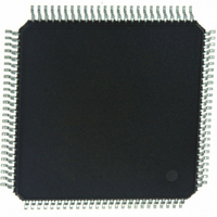
Z16F2811AL20SG Zilog, Z16F2811AL20SG Datasheet - Page 158

Z16F2811AL20SG
Manufacturer Part Number
Z16F2811AL20SG
Description
IC ZNEO MCU FLASH 128K 100LQFP
Manufacturer
Zilog
Series
Encore!® ZNEOr
Specifications of Z16F2811AL20SG
Core Processor
ZNEO
Core Size
16-Bit
Speed
20MHz
Connectivity
EBI/EMI, I²C, IrDA, LIN, SPI, UART/USART
Peripherals
Brown-out Detect/Reset, DMA, POR, PWM, WDT
Number Of I /o
76
Program Memory Size
128KB (128K x 8)
Program Memory Type
FLASH
Ram Size
4K x 8
Voltage - Supply (vcc/vdd)
2.7 V ~ 3.6 V
Data Converters
A/D 12x10b
Oscillator Type
Internal
Operating Temperature
0°C ~ 70°C
Package / Case
100-LQFP
Processor Series
Z16F2x
Core
Zneo
Data Bus Width
16 bit
Data Ram Size
4 B
Interface Type
ESPI, I2C, UART
Maximum Clock Frequency
20 MHz
Number Of Programmable I/os
76
Number Of Timers
4
Operating Supply Voltage
2.7 V to 3.6 V
Maximum Operating Temperature
+ 70 C
Mounting Style
SMD/SMT
Development Tools By Supplier
Z16F2800100ZCOG
Minimum Operating Temperature
0 C
On-chip Adc
10 bit, 12 Channel
For Use With
770-1003 - ISP 4PORT FOR ZILOG ZNEO MCU269-4537 - DEV KIT FOR Z16F ZNEO
Lead Free Status / RoHS Status
Lead free / RoHS Compliant
Eeprom Size
-
Lead Free Status / Rohs Status
Details
Other names
269-4533
Available stocks
Company
Part Number
Manufacturer
Quantity
Price
Company:
Part Number:
Z16F2811AL20SG
Manufacturer:
VISHAY
Quantity:
9 487
Part Number:
Z16F2811AL20SG
Manufacturer:
ZILOG
Quantity:
20 000
- Current page: 158 of 388
- Download datasheet (22Mb)
PS022008-0810
1
0
Idle State
of Line
Figure 27. LIN-UART Asynchronous MULTIPROCESSOR Mode Data Format
The character format is given below:
In MULTIPROCESSOR (9-bit) mode, the
MULTIPROCESSOR control bit. The LIN-UART Control 1 and Status 1 registers provide
MULTIPROCESSOR (9-bit) mode control and status information. If an automatic address
matching scheme is enabled, the LIN-UART address compare register holds the network
address of the device.
MULTIPROCESSOR (9-bit) Mode Receive Interrupts
When MULTIPROCESSOR mode is enabled, the LIN-UART processes only frames
addressed to it. You can determine whether a frame of data is addressed to the LIN-UART is
made in hardware, software or a combination of the two, depending on the multiprocessor
configuration bits. In general, the address compare feature reduces the load on the CPU
because it does not need to access the LIN-UART when it receives data directed to other
devices on the multi-node network. The following 3 MULTIPROCESSOR modes are
available in the hardware:
1. Interrupt on all address bytes.
2. Interrupt on matched address bytes and correctly framed data bytes.
3. Interrupt only on correctly framed data bytes.
These modes are selected with MPMD[1:0] in the LIN-UART Control 1 register. For all
MULTIPROCESSOR modes, bit MPEN of the LIN-UART Control 1 register must be set to 1.
The first scheme is enabled by writing
address bytes cause an interrupt, while data bytes never cause an interrupt. The ISR checks
the address byte which triggered the interrupt. If it matches the LIN-UART address, the
software clears MPMD[0]. At this point, each new incoming byte interrupts the CPU. The
software determines the end of the frame and checks for it by reading the MPRX bit of the
LIN-UART Status 1 register for each incoming byte. If MPRX
the address of this new frame is different from the LIN-UART’s address, then MPMD[0]
must be set to 1 by software, causing the LIN-UART interrupts to go inactive until the next
Start
Bit0
lsb
Bit1
Bit2
P R E L I M I N A R Y
Bit3
Data Field
Bit4
01b
Parity
to MPMD[1:0]. In this mode, all incoming
Bit5
bit location (9th bit) becomes the
Bit6
msb
Bit7
=1
, a new frame has begun. If
Product Specification
ZNEO
MP
1
Stop Bit(s)
Z16F Series
2
LIN-UART
142
Related parts for Z16F2811AL20SG
Image
Part Number
Description
Manufacturer
Datasheet
Request
R

Part Number:
Description:
High Performance Microcontrollers
Manufacturer:
ZiLOG Semiconductor
Datasheet:

Part Number:
Description:
Communication Controllers, ZILOG INTELLIGENT PERIPHERAL CONTROLLER (ZIP)
Manufacturer:
Zilog, Inc.
Datasheet:

Part Number:
Description:
KIT DEV FOR Z8 ENCORE 16K TO 64K
Manufacturer:
Zilog
Datasheet:

Part Number:
Description:
KIT DEV Z8 ENCORE XP 28-PIN
Manufacturer:
Zilog
Datasheet:

Part Number:
Description:
DEV KIT FOR Z8 ENCORE 8K/4K
Manufacturer:
Zilog
Datasheet:

Part Number:
Description:
KIT DEV Z8 ENCORE XP 28-PIN
Manufacturer:
Zilog
Datasheet:

Part Number:
Description:
DEV KIT FOR Z8 ENCORE 4K TO 8K
Manufacturer:
Zilog
Datasheet:

Part Number:
Description:
CMOS Z8 microcontroller. ROM 16 Kbytes, RAM 256 bytes, speed 16 MHz, 32 lines I/O, 3.0V to 5.5V
Manufacturer:
Zilog, Inc.
Datasheet:

Part Number:
Description:
Low-cost microcontroller. 512 bytes ROM, 61 bytes RAM, 8 MHz
Manufacturer:
Zilog, Inc.
Datasheet:

Part Number:
Description:
Z8 4K OTP Microcontroller
Manufacturer:
Zilog, Inc.
Datasheet:

Part Number:
Description:
CMOS SUPER8 ROMLESS MCU
Manufacturer:
Zilog, Inc.
Datasheet:

Part Number:
Description:
SL1866 CMOSZ8 OTP Microcontroller
Manufacturer:
Zilog, Inc.
Datasheet:

Part Number:
Description:
SL1866 CMOSZ8 OTP Microcontroller
Manufacturer:
Zilog, Inc.
Datasheet:

Part Number:
Description:
OTP (KB) = 1, RAM = 125, Speed = 12, I/O = 14, 8-bit Timers = 2, Comm Interfaces Other Features = Por, LV Protect, Voltage = 4.5-5.5V
Manufacturer:
Zilog, Inc.
Datasheet:


